EM500 Open-Loop Vector Control Inverter User Manual
424
frames, as recessive, said the transmission of remote frames.
The control segment (DLC) consists of 6 bits, including reserved bits r1, r0, and 4-bit
DLC data length codes, in the range 0 to 8, which can also be transmitted on the bus
when the DLC value is greater than 8 The number of bytes transferred in the data field for
this frame is still limited to 8 bytes.
The data segment consists of 0 to 64 bits and contains the actual valid information (0-8
bytes) for this frame transmission.
The data segment is followed by a CRC segment consisting of a 15-bit CRC sequence
and a 1-bit CRC delimiter. The receiver may use the CRC sequence to identify whether or
not erroneous data has been accepted.
The acknowledgment segment consists of an acknowledge slot bit and an acknowledge
delimiter bit. The transmitter transmits a recessive level at the acknowledge slot; after
receiving the complete message correctly, the receiver sends a dominant level for
acknowledgment.
By the end of the frame composed of seven recessive level.
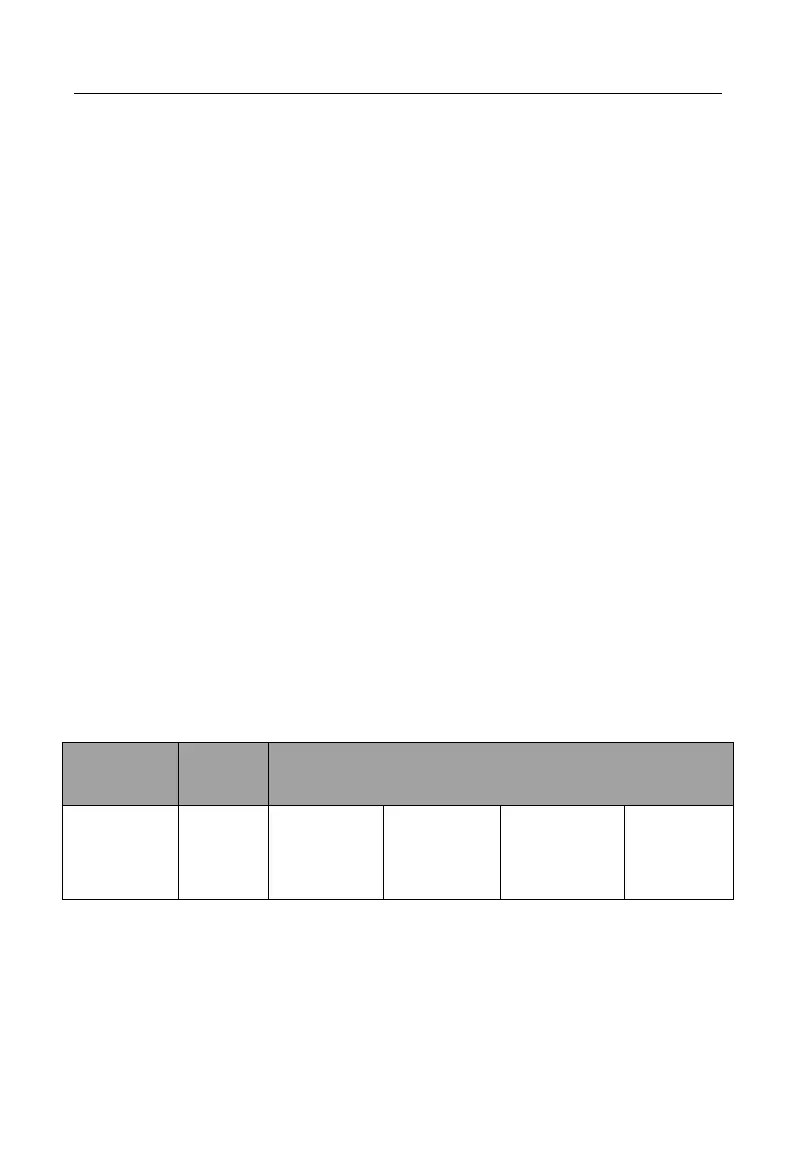
In the standard frame of a frame of data, users only need to focus on the contents of the
identifier, control section and the data segment. The definition data format is as
follows:
Function
code + slave
address
The 11-bit identifier consists of a 4-bit function code and a 7-bit node address. The
node address ranges from 0 to 127, where 0 is the broadcast address. 127 for the host
address, the specific function code is defined in the table below.