EM500 Open-Loop Vector Control Inverter User Manual
245
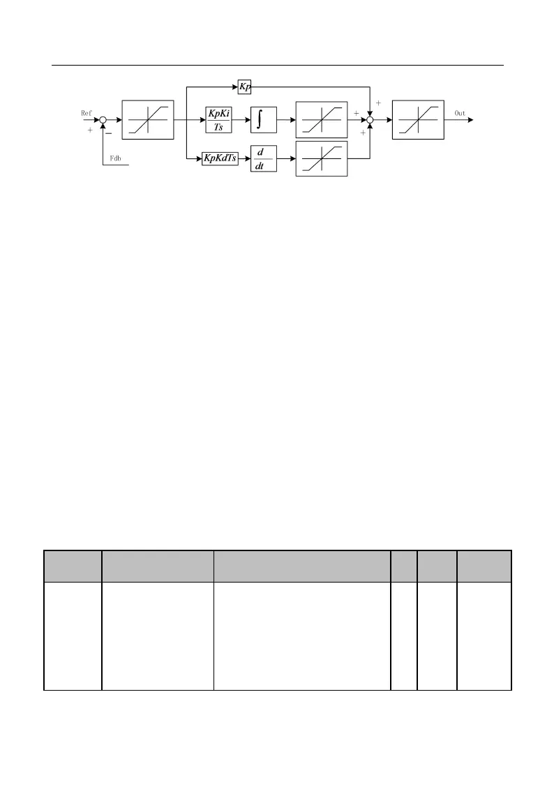
Figure 7-27 Process PID Block Diagram
PID control is a closed loop control mode. The output signal (Out) of the controlled
object of the system is fed back to PID controller, which adjusts the output of the
controller through PID arithmetic and forms a closed loop or multiple closed loops. By
using PID control, the output value and the set target value of the controlled object are
consistent. See Figure 7-27 for the functional block diagram.
PID controller implements the control by calculating the three calculation factors,
i.e., P (proportional), I (integral) and D (differential) and on the basis of the dispersion
between target (Ref) and feedback signal. The features of various calculation factors are
as follows:
P (proportion):
Proportional control is the easiest control mode. Output error signal and input error
signal of its control are proportional. The system outputs the stable error when inverter is
in the proportional control only.
I (integral):
The integrals of output error signal and input error signal of the controller are
directly proportional. This control mode can eliminate the stable error and enable the
system to be free from stable error after entering the stable status. However, under this
mode, inverter can not track intense changes.
D (Differential):
The differential values of output error signal and input error signal of the controller
are directly proportional. Its controller can predicate the trend of error changes and
respond to intense changes to improve the dynamic characteristics of the system in the
regulation process.
0: Numeric PID Setting
1: AI1
2: AI2
3: AI3
4: AI4 (Expansion Card)
5:
PULSE
High-Frequency Pulse (X7)
6: Communication Percentage Setting