EM500 Open-Loop Vector Control Inverter User Manual
54
leakage current should be less than the holding current of the contactor or relay under
control), VDR and fly-wheel diode (for DC electromagnetic circuit, please pay attention
to the polarity at installation). Components of absorption circuit should be installed near
two sides of relay or contactor coil.
3.3.6Wiring of Multi-function Output Terminal
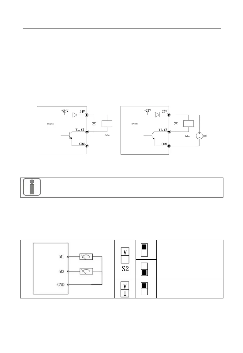
Y1 and Y2 can be powered by internal 24V power supply or external power supply
(see Figure 3–17).
a: internal power supply b: external power supply
Figure 3-18 Wiring of Multi-function Output Terminal
1. An antiparallel diode must be added, in order to use an internal power
supply (see Figure 3-18-a).
3.3.7Analog Output Terminal Wiring
External analog board of analog output terminals M2 may indicate multiple physical
quantities. Select (0 - 20 mA) or (0 - 10 V) by DIP switch; M2 corresponds to S3. M1 is
analogy output ONLY for DC 0~10V. Wiring of DIP switch and terminal is as follows:
Switch is invalid ,M1 for
analog voltage output
M2 for analog voltage
output