EM500 Open-Loop Vector Control Inverter User Manual
442
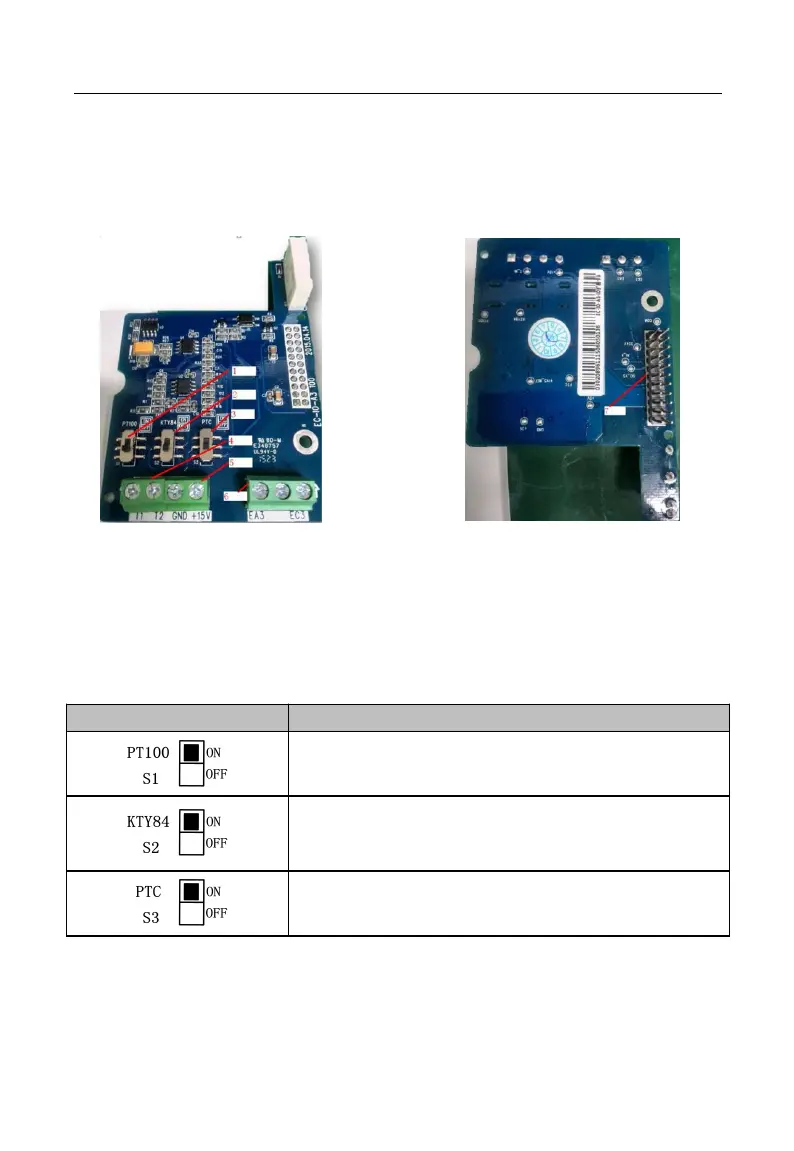
Figure 2 Installation of IO Expansion Card 3
Point I/O expansion card 3 at interface and location hole of expansion slot, and fix
them with screws.
Figures of real objects are as follows:
Elevation Back Elevation
1. DIP Switch 1 2. DIP Switch 2 3. DIP Switch 3
4. Temperature Sensor 5. Power Supply 6. Relay Output 7. Inverter Slot
II.3 Expansion Terminal Function
Table 3 IO Expansion Card 3 Terminal Function
S1-ON: T1-T2 temperature sensor type: PT100
S2 and S3 should be OFF
S2-ON: T1-T2 temperature sensor type: KTY84-130 or
KTY84-150
S1 and S3 should be OFF
S3-ON: T1-T2 temperature sensor type: PTC130 or PTC150
S1 and S2 should be OFF