EM500 Open-Loop Vector Control Inverter User Manual
173
The carrier frequency is set through F00.23, limited by maximum carrier and will
not change during running.
F00.24=1: Enabled 1
The carrier frequency set through F00.23 is affected by inverter temperature and
load level. If inverter has an excessively high temperature or load, the carrier wave will
be limited. When the set carrier frequency F00.23 is greater than the limit value, the limit
value shall be used as the carrier frequency of inverter.
F00.24=2: Enabled 2
Conduct carrier frequency self-tuning based on the setting of F00.23.
Carrier Frequency
Noise Suppression
Noise Suppression
Intensity
When noise suppression function is enabled (F00.25=1), a sine wave may be
superposed on the basis of the set carrier wave (the frequency is set through F00.26 and
the intensity is set through F00.27), which may suppress present motor noise to some
extent.
0: Motor 1 Parameter
1: Motor 2 Parameter
EM500 inverter supports the time interval based control of two motors, of which
motor parameter and control parameter can be set separately. Motor 1 corresponds to
parameters of F00, F01 and F06, and motor 2 corresponds to parameters of F14.
In combination with the input function “30: Switch between Motor 1 and Motor 2”,
F00.28 can be used to select present motor (see Table 7-3 for details).
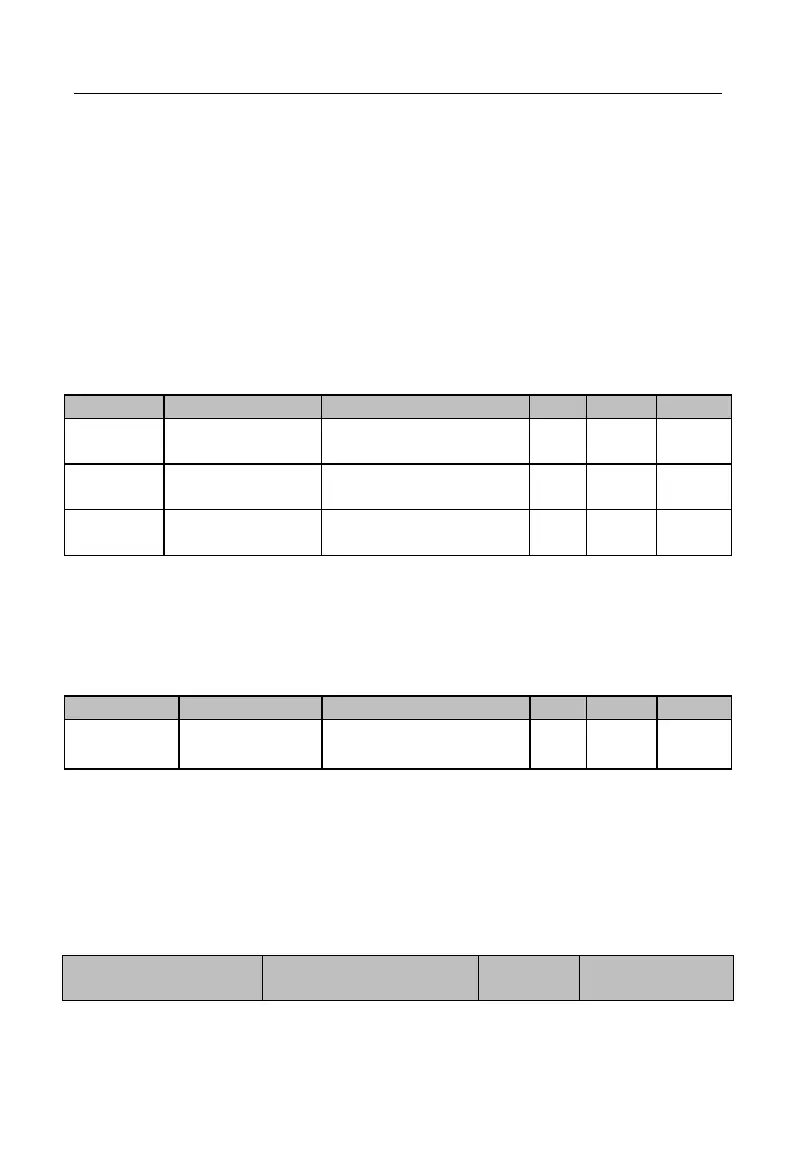
Table 7-3 Motor Parameter Group Selection
F00.28: Motor
Parameter Group
30: Switch between
Motor 1 and Motor 2