EM500 Open-Loop Vector Control Inverter User Manual
20
As indicated in Figure 1-3, when auxiliary frequency source B is being set, the
setting of F00.05 will be based upon to determine present setting channel. Process PID
and Simple PLC can participate in the setting.
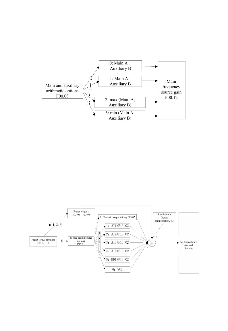
Figure 1-4 Main and Auxiliary Arithmetic Setting
As indicated in Figure 1-4, main and auxiliary arithmetic can be classified into four
categories. At this time, both main and auxiliary settings are enabled.
Torque setting mode: Motor current is taken as the control object.
Torque setting mode can be set by multiple ways, which include numeric setting,
analog input setting, high-speed pulse input setting, communication setting, digital
potentiometer setting and preset torque setting. In Figure 1-5, various input modes for
torque setting of EM500 are described.
Figure 1-5 Torque Setting Mode