EM500 Open-Loop Vector Control Inverter User Manual
33
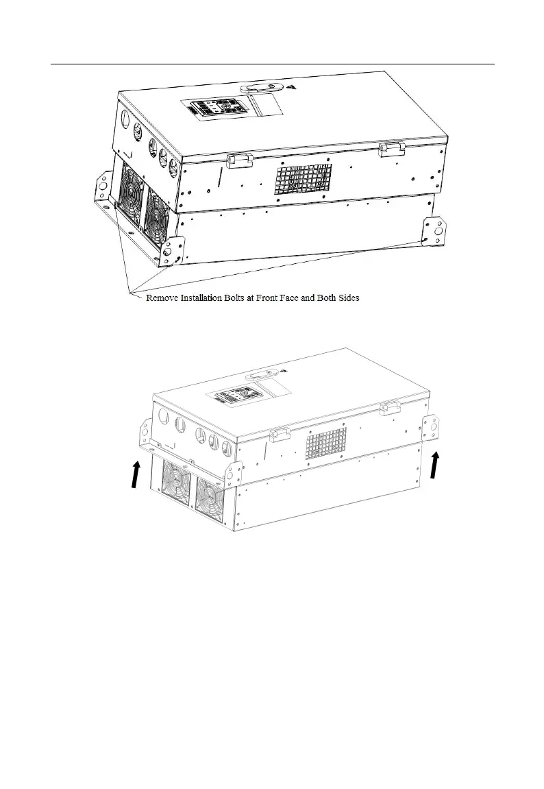
Figure 2-5 Disassemble Top and Bottom Mounting Holes
Figure 2-6 Assemble Top and Bottom Mounting Holes
Installation of EM500 inverter (below 22kW): As shown in 2-7, insert left and right
accessories for flush mounting into the slots at the left and right sides of the plastic shell,
and tighten the two front and back screws. See Figure 2-8 Installation Dimensions for
Flush Mounting and Table 2–3 for installation dimensions.