EM500 Open-Loop Vector Control Inverter User Manual
167
Auxiliary Channels
5: High-Frequency Pulse
(PULSE) * Synthetic
Frequency of Main and
Auxiliary Channels
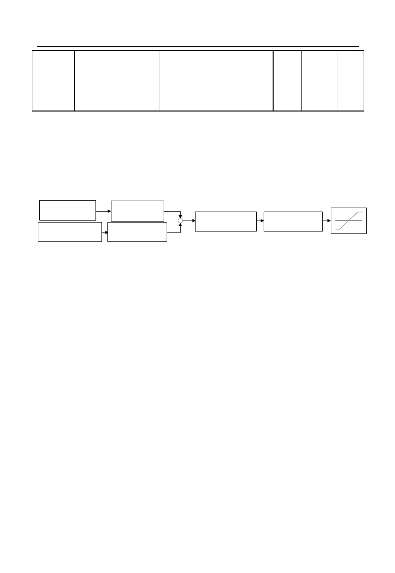
The parameters above are mainly used to adjust the gain of various setting sources
(refer to Figure 7-3). Both main frequency source A and auxiliary frequency source B
have the setting gain; there is the synthetic gain by combination with the selected
function code F00.06. The final setting is limited by analog adjustment input, upper limit
frequency and lower limit frequency.
主频率源A给定
F00.04等
辅助频率源B给定
F00.05等
主频率源增益
F00.10
辅助频率源增益
F00.11
主辅助频率源合
成增益F00.12
合成频率的模拟
量调节F00.13
限幅
Main frequency source
A Setting (including
F00.04)
Main frequency source
gain F00.10
Synthesis
(including F00.06)
Synthetic gain of main and
auxiliary frequency source
F00.12
Analog quantity
adjustment of synthetic
frequency F00.13
Limit
Auxiliary frequency source
B setting (including F00.05)
Auxiliary frequency
source gain F00.11
Figure 7-3 Frequency Source Setting Control (Gain Description)
The action mode of function codes about gain (F00.10 - F00.12) is “multiply”, i.e.,
“Setting=Former setting * gain”. The following will describe the analog input adjustment
of synthetic frequency (F00.13).
F00.13=0: Synthetic Frequency of Main and Auxiliary Channels
Synthetic frequency is directly set by the synthetic frequency of main and auxiliary
channels.
F00.13=1: AI1* Synthetic Frequency of Main and Auxiliary Channels
F00.13=2: AI2* Synthetic Frequency of Main and Auxiliary Channels
F00.13=3: AI3 * Synthetic Frequency of Main and Auxiliary Channels
F00.13=4: AI4 (Expansion Card) * Synthetic Frequency of Main and Auxiliary
Channels
The synthetic frequency is determined through “AI (percentage) * Synthetic
Frequency of Main and Auxiliary Channels”.
F00.13=5: High-Frequency Pulse (X7) * Synthetic Frequency of Main and
Auxiliary Channels