EM500 Open-Loop Vector Control Inverter User Manual
155
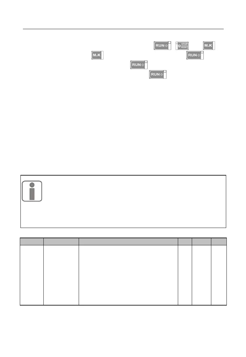
F00.02=0: Keypad Control (LOC/REM indicator on)
The start and stop of inverter will be controlled with , and of
keypad. Under no fault, press to enter jog running mode or press to enter
running mode. When the green LED above the button is always on, it means
that inverter is running; when the green LED above the button flickers, it means
that inverter is in the ramp-to-stop status.
No matter whether the reference input of the control mode is speed or torque,
inverter always runs at jog input speed control mode as long as jog is enabled.
F00.02=1: Terminal Control (LOC/REM indicator off)
The start/stop control terminal defined through F02.00 - F02.06 controls the start
and stop of inverter; the detailed configurations of the terminal control are defined
through F00.03.
F00.02=2: Communication Control (LOC/REM indicator flickers)
The host controller controls inverter to start and stop through RS485 communication
interface. See 7000H in 12.3.4 Allocation of Register Address for detail.
The final command source is also determined by either “24: Switch
Run Command to Keypad” or “25: Switch Run Command to
Communication”. When the input function “24: Switch Run
Command to Keypad” is enabled, present command source is
“Keypad Control”. When the input function “25: Switch Run Command to
Communication” is enabled, present command source is “Communication
Control”. Otherwise, the final command source is determined through F00.02.
Terminal
Control
Mode
Options
0: Terminal RUN for running,
Forward/Reverse (F/R)
1: Terminal RUN for forward, F/R
reverse
2: Terminal RUN for forward, Xi stop,
F/R reverse
3: Terminal RUN for running, Xi stop
Forward/Reverse (F/R)