EM500 Open-Loop Vector Control Inverter User Manual
222
or excessive, this will result in oscillation due to over regulation.
User shall adjust the aforesaid PI parameters according to actual load characteristics.
Generally, user shall increase ASR_P as possible and regulate ASR_T, so as to enable the
system to response quickly without over control.
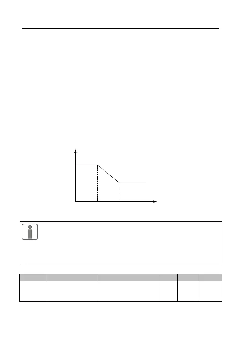
To enable the system to have a quick dynamic response at both low speed and high
speed, it's required to perform PI regulation at both speed modes. In actual running, the
speed regulator would automatically calculate present PI parameter according to present
frequency. If present PI parameter is below the switching frequency 1, the speed PI
parameter is P1, T1; if above the switching frequency 2, the speed parameter PI is P2, T2.
If greater than the switching frequency 1(F06.04), but less than the switching frequency 2
(F06.05), the movement from switching frequency 1 to switching frequency 2 presents a
linear transition procedure. See Figure 7-22 for details.
P1,Ti1
P2,Ti2
PTD parameter
Switching frequency 1 Switching frequency 2 Feedback frequency
Figure 7-22 PI Parameter
1. Generally, user does not need to adjust F06.00 - F06.05 parameters,
so please pay enough attention when you decide to adjust these
2. While setting the switching frequency, please note that the switching
frequency 1 (F06.04) must be lower than or equivalent to the switching
frequency 2 (F06.05).
Speed Loop
Anti-Saturation
Factor