EM500 Open-Loop Vector Control Inverter User Manual
266
EM500 series inverter supports 4 different baud rates.With the upper computer or
multi-machine communication, the inverter / host computer needs to be set to the same
baud rate. The baud rate will affect the communication distance See Chapter 13 for more
information.
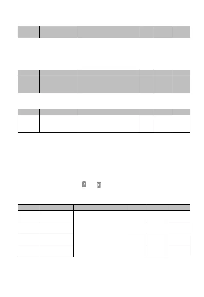
CANSinee
Communication
timeout
0.0 - 60.0, 0.0: Disabled (also
works for master - slave
system)
CANSinee protocol communication, Communication timeout setting, See the
Modbus Communication Timeout function explanation
0
~
10
:
default for debugging
11: No trigger write before
debugging
For the PLC or HMI with inverter after equipment debugging is completed, set F10.56 =
11, then all write data isn’t stored; PLC communication can avoid writing EEPROM.
If parameters should be saved after power off please setting F10.56 = 0.
7.12 F11 Group: User-Defined Parameter
First, by setting F11, user may select a function code and enter the user-defined
mode (--U--, see 4.2.2). Through and , user may switch to the desired function
code circularly. This function is mainly applied to occasions of less than 32 function
codes so as to avoid troubles of too many function codes.
The content displays
Uxx.xx, which means
that Fxx.xx function code
is selected. If the keypad
displays U00.00 at the
time of entering the
function code F11.00, it
means that the first