EM500 Open-Loop Vector Control Inverter User Manual
63
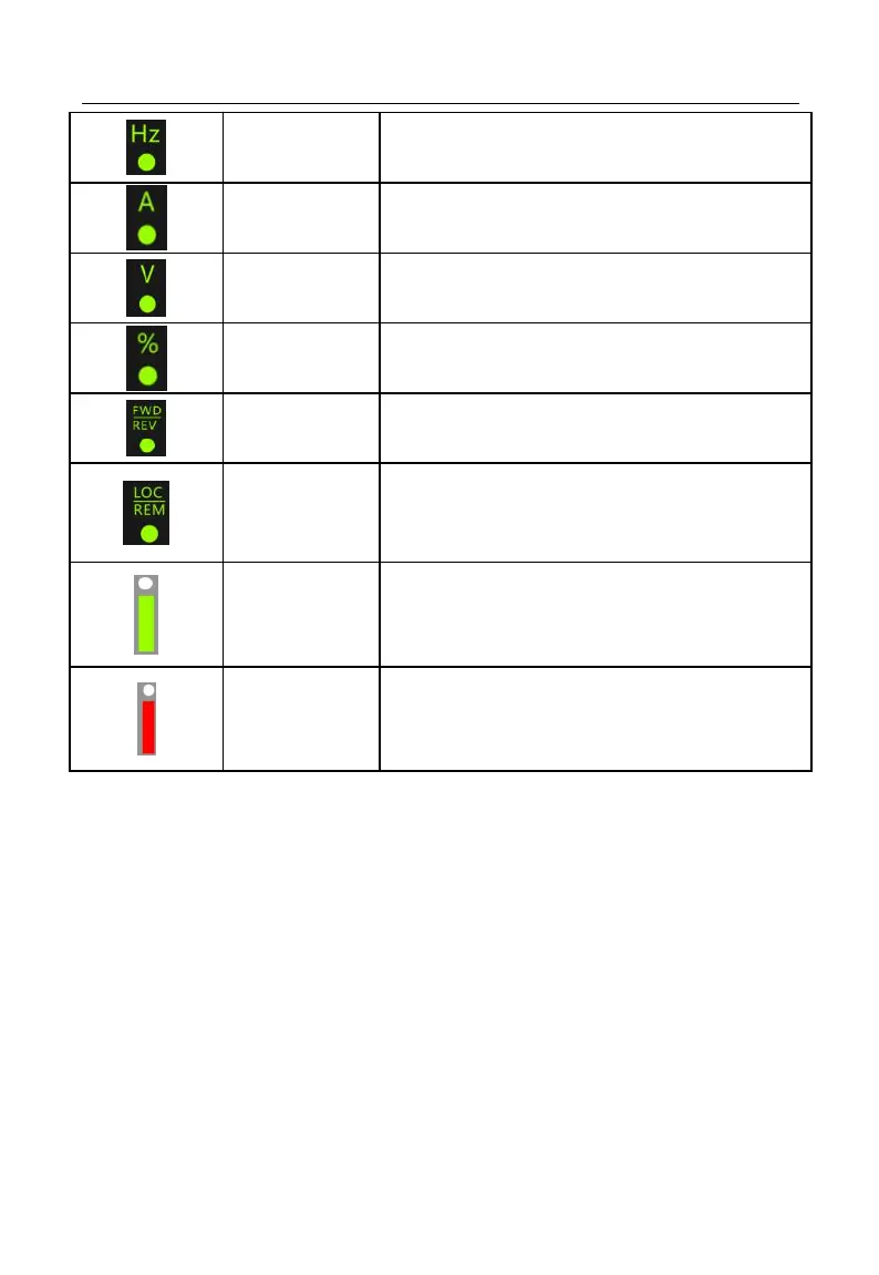
On when present parameter is frequency.
On when present parameter is current.
On when present parameter is voltage.
On when present parameter is percentage.
On at frequency is negative.
On at running is reversed
Communication
Control Indicator
On when F00.02 is set to keypad control,
Off when F00.02 is set to terminal control
Flickers when F00.02 is set to communication
control
On when inverter is running
Flickers when stopping, off after stop.
On when inverter is in fault state.
4.2 LED Keypad Operation Mode
4 menu levels of LED keypad: Monitoring (level 0), menu mode selection (level 1),
function code selection (level 2) and parameter value (level 3). In the following parts,
menu levels are represented by figures.
3 parameter display modes: All menu mode (--A--) displays all function codes;
user-defined mode (--U--), only displays function parameters selected by user through
F11 group; non-factory defaults (--C--), only displays those function codes that are
different from factory setting.