EM500 Open-Loop Vector Control Inverter User Manual
55
M2 for analog current
output
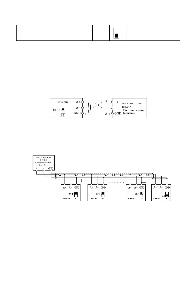
3.3.8 Wiring of 485 Communication Terminal
Communication terminals A+ and A- are RS485 communication interfaces of
inverter. Realize networking control of host controller (PLC or PLC controller) and
inverter by connecting to host controller for communication. RS485, RS485/RS232
converter and EM500 inverter are wired as shown in Figures 3-18, 3-19 and 3-20.
RS485 terminal of single inverter directly connects to host controller for
communication:
Figure 3-19 Wiring of Single Inverter Communication Interface
RS485 terminals of multiple inverters connect to host controller for
communication:
Figure 3-20 Wiring of Communication Interfaces of Multiple Inverters
Connect to host controller for communication through RS485/RS232 converter