EM500 Open-Loop Vector Control Inverter User Manual
57
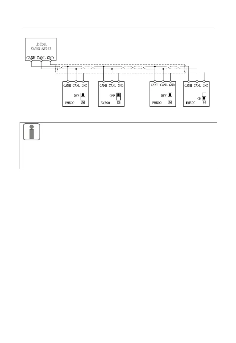
Figure 3 23 CANSinee communication wiring of several inverters
1. Multiple inverter CANSinee communication using terminal board RJ45
interface connection, the connection should pay attention to RJ45 interface input and
output sequence should be consistent, in accordance with the "No. 1 machine port 2--2
machine port 1-2-2 machine port 2 - 3 port 1 ".
3.3.10 Control Circuit Cable and Screw Size
The length of cable for transmitting control signal should be limited to 50 m
and its distance from power cable should be greater than 30 cm, in order to
reduce interference and attenuation of control signal. Please use shielded
twisted-pair cable when analog signal is input externally.
It’s recommended to use 0.5 - 1 mm
2
cable as the control circuit cable.
Terminal block of EM500 inverter shall be through control circuit connection
terminal. Please use a cross screwdriver PH0 for installation with tightening
torque of 0.5 N.m.
3.3.11Attentions for Control Circuit Wiring
Separate control circuit cable from other cable.