EM500 Open-Loop Vector Control Inverter User Manual
280
inputted through F13.02 (Numeric Torque Setting).
F13.01=6: Communication Percentage Setting
The torque is determined by communication, etc
If inverter is under master-slave communication control (F10.05=1) and present
inverter is a slave (F10.06=0), the set percentage is “700FH (Master-Slave
Communication Setting) * F10.08 (Receiving Proportionality Factor of Slave)”.
The range of 700FH is -100.00% to 100.00%. See Table 12-2 for details.
For general communication (F10.05=0), the set percentage is “7003H (Torque
Communication Setting) * F00.18 (Numeric Torque Setting)”. The range of 7003H
is -200.00% to 200.00%. See Table 12-2 for details
F13.01=8: Digital Potentiometer Setting
Torque mode, the torque given directly by the digital potentiometer, the specific
value can see F12.43
To realize the diversification of the torque application, EM500 inverter supports the
preset torque function. Set the input terminal “17: Preset Torque Terminal 1” and “18:
Preset Torque Terminal 2”. See Table 7-19 for details
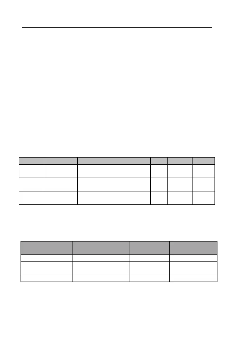
Table 7-19 Preset Torque Commands and Preset Torque Terminals
18: Preset Torque
Terminal 2
17: Preset Torque
Terminal 1