EasyManua.ls Logo

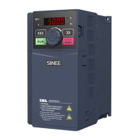
Sinee EM100-0R4-1B User Manual

Sinee EM100-0R4-1B
120 pages
To Next Page IconTo Next Page
Page #1 background imageLoading...
Page #1 background image
User Manual
EM100 Mini Inverter
1
Preface
Thank you for purchasing EM100 series mini inverter.
Document No.: 31010008
Version No.:103
Issue Date: 06/03/2013
EM100 mini inverter is a compact, intuitive, reliable and performing AC variable speed
drive for 3-phase induction motors.
This manual offers the general information of installation, wiring, function parameters,
daily maintenance, and fault diagnosis of EM100 mini inverter.
It is the duty of any user to perform the appropriate, correct installation or configuration
of the optional parameters of the devices. Neither SINEE nor its distributors shall be
responsible or liable for misuse of the information contained herein or mismatching the
inverter with the motor.
In the interests of commitment to a policy of continuous development and improvement,
SINEE reserves the right to update the specification of the product or its performance, or
the content herein without notice.
More updates and information are available at www.sinee.cn.

Table of Contents

Question and Answer IconNeed help?

Do you have a question about the Sinee EM100-0R4-1B and is the answer not in the manual?

Sinee EM100-0R4-1B Specifications

General IconGeneral
BrandSinee
ModelEM100-0R4-1B
CategoryInverter
LanguageEnglish

Summary

Preface

Safety Information

1.1 Safety Precautions

Detailed safety precautions before installation.

1.2 Precautions

General safety warnings for operation and maintenance.

Overview

2.1 Verifying Product

Steps to verify the product upon receipt.

2.2 Model Numbering Scheme and Nameplate

Explanation of model numbers and nameplate details.

2.4 Technical Specifications

Detailed technical specifications of the inverter.

2.6 Overall and Installation Dimensions

Physical dimensions and mounting requirements.

Installation

3.1 Mechanical Installation

Guidelines for physically installing the inverter.

3.2 Wiring

General guidelines and safety for wiring.

Keypad Operation

4.1 Keypad

Description of the keypad layout and components.

4.2 Function Code Check and Editing Method

Procedures for navigating and editing parameters.

Parameter Description

F00 Group: General Parameters

Core operational and setting parameters.

F01 Group: Motor Parameters

Parameters specific to the connected motor.

F02 Group: Input Terminal Function Terminals

Configuration of digital and analog input terminals.

F03 Group: Output Terminal Parameters

Configuration of digital and analog output terminals.

F04 Group: Start/Stop Control Parameters

Parameters for controlling inverter start and stop behavior.

F05 Group: V/F Control Parameters

Parameters for Volts/Hertz control.

F06 Group: Auxiliary Function Parameters

Parameters for additional functions.

F07 Group: Fault and Protection Parameters

Parameters for inverter protection and fault management.

F08 Group: Preset Speed and PLC Parameters

Parameters for preset speed and program operation.

F09 Group: Process PID Parameters

Parameters for Proportional-Integral-Derivative control.

F10 Group: Communication Parameters

Parameters for inverter communication settings.

F11 Group: User Parameters

Customizable user parameters.

Monitoring Parameters

C00.00 Output Frequency

Displays the current output frequency.

C00.01 Actual Output Voltage

Displays the actual output voltage.

C00.02 Actual Output Current

Displays the actual output current.

C00.05 DC Bus Voltage

Displays the DC bus voltage.

C00.12 Input Terminal Status

Shows logic status of external input terminals.

C00.13 Output Terminal Status

Shows logic status of output terminals.

C00.16 Inverter Heatsink Temperature

Displays inverter heatsink temperature.

Troubleshooting

7.1 Fault and Corrective Action

Lists common faults, causes, and corrective actions.

7.2 Common Fault and Troubleshooting

General troubleshooting for common issues.

EMC (Electromagnetic Compatibility)

8.3 EMC Guide

Guidelines for ensuring EMC compliance.

Maintenance and Inspection

9.1 Maintenance and Inspection

Procedures for routine maintenance and inspection.

9.2 Outline of Warranty

Information regarding the product warranty.

Appendix A: EM100 Modbus Communication Protocol

4. Explanation of Command

Details Modbus commands for reading/writing parameters.

5.3 Allocation of Register Addresses

Maps function codes to register addresses.

5.5 Error Message Response

Describes inverter responses to communication errors.

6. Example

Provides examples of Modbus communication.

Appendix B: Accessories

1. Selecting Braking Resistor

Guidelines for choosing appropriate braking resistors.

2. Optional Installation Accessories

Lists available accessories for installation.

Related product manuals