EM500 Open-Loop Vector Control Inverter User Manual
52
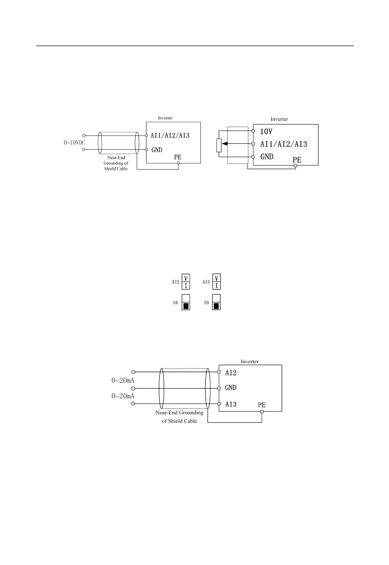
When analog voltage input signal is powered by external power supply, terminals
AI1, AI2 and AI3 are wired as Figure 3-14-a.
When analog voltage input signal is generated by potentiometer, terminals AI1, AI2
and AI3 are wired as Figure 3-14-b.
(a) (b)
Figure 3-14 Wiring of Terminals AI1, AI2 and AI3
3.3.3.2 Wiring Terminals AI2 and AI3 (Input Analog Current Signal):
When selecting analog current signal input on terminals AI2 and AI3, configure
current mode through switches S4 and S5 of the terminal block. See Figure 3–15 for
detail.
Figure 3-15 Configuring Current Modes with S4 and S5
3.3.4 Wiring of Terminals AI2 and AI3 (as shown in Figure 3-15)
Figure 3-16 Wiring of Terminals AI2 and AI3
3.3.5Wiring of Multi-function Input Terminal
Multi-function input terminals of EM500 inverter adopt full bridge rectifier. PLC
terminal is a common terminal for X1-X7. The current passing through PLC terminal can