EM500 Open-Loop Vector Control Inverter User Manual
422
13. CANSinee Communication Protocol
1. Applicable series: EM500
2.Applicable network: Inverter with CAN bus interface - Inverter master-slave
communication, and communication between client and inverter
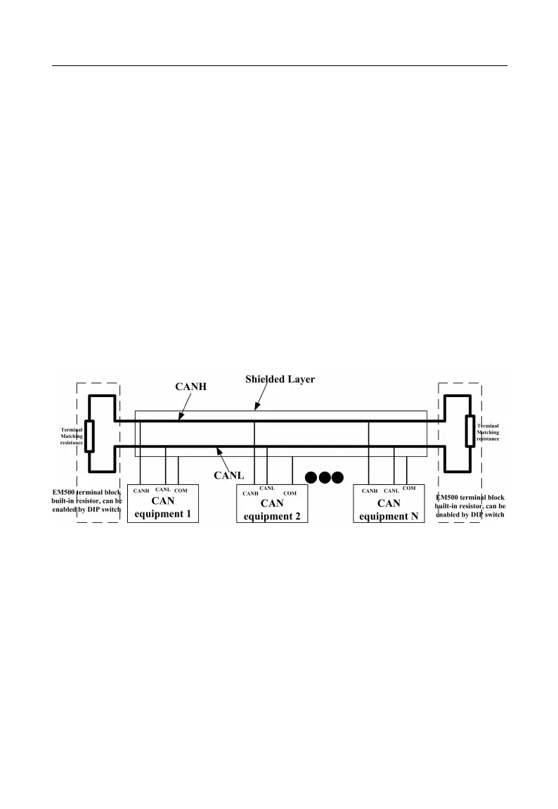
CAN bus connection topology as shown below, CAN bus recommended shielded twisted
pair connection, the bus ends are connected to two 120Ω termination resistor to prevent
signal reflection. Shield generally use a single point of reliable grounding.
Figure 13- 1 CAN bus topology diagram
13.2.2 Baud rate and transmission distance
The maximum length of the CAN bus depends on the communication speed, Specific
provisions are as follows: