EasyManua.ls Logo

Sinee EM500 - Main Circuit Cable and Terminal Screw Size; Wiring Distance and Carrier Frequency between Inverter and Motor; Wiring Distance between Inverter and Motor

Sinee EM500
459 pages
Print Icon
To Next Page IconTo Next Page
To Previous Page IconTo Previous Page
Loading...
EM500 Open-Loop Vector Control Inverter User Manual
46
3.2.6.9Wiring Distance Between Inverter and Motor
The longer the wiring distance between inverter and motor is, the higher the carrier
frequency will be and the greater the high-frequency harmonic leakage current on its
cable will be accordingly. As a result, an adverse impact can be produced upon inverter
and its devices nearby. Adjust the carrier frequency by reference to table 3–3 to reduce
the high-frequency leakage current.
If motor cable is over 50m, connect a 3-phase inverter output AC reactor of the same
capacity to terminals U, V or W of inverter.
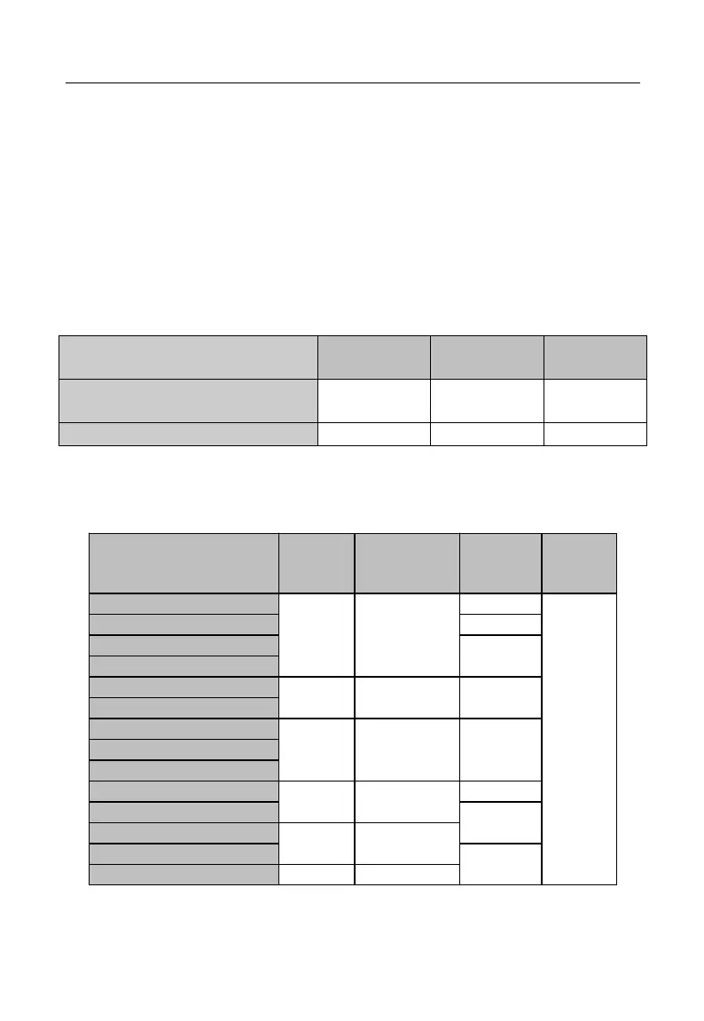
Table 3-3 Wiring Distance and Carrier Frequency Between Inverter and motor
Wiring Distance Between Inverter
and Motor
Below 50 m
Below 100 m
Above 100
m
Carrier Frequency
Below 10 kHz
Below 8 kHz
Below 5
kHz
F00.23
10.0
8.0
5.0
3.2.7Main Circuit Cable and Terminal Screw Size
Main circuit cable and terminal screw sizes are shown in Table 3–4.
Table 3-4 Cable and Terminal Screw Specifications
Model No.
Terminal
Screw
Tightening
Torque (N.m)
Cable
Size (mm
2
)
Cable
Type
EM500-0R7G/1R5P-1B/2B/3B
M3.5
1.2 - 1.5
1.5
750 V cable
EM500-1R5G/2R2P-1B/2B/3B
2.5
EM500-2R2G/3R0P-1B/2B/3B
4
EM500-4R0G/5R5P-3B
EM500-5R5G/7R5P-3B
M4
1.5 - 2.0
6
EM500-7R5G/9R0P-3B
EM500-011G/015P-3B
M5
3.0 - 4.0
10
EM500-015G/018P-3B
EM500-018G/022P-3B
EM500-022G/030P-3/3B
M6
4.0 - 5.0
16
EM500-030G/037P-3/3B
25
EM500-037G/045P-3/3B
M8
9.0 - 10.0
EM500-045G/055P-3/3B
35
EM500-055G/075P-3/3B
M10
17.0 –22.0

Table of Contents

Related product manuals