EM500 Open-Loop Vector Control Inverter User Manual
239
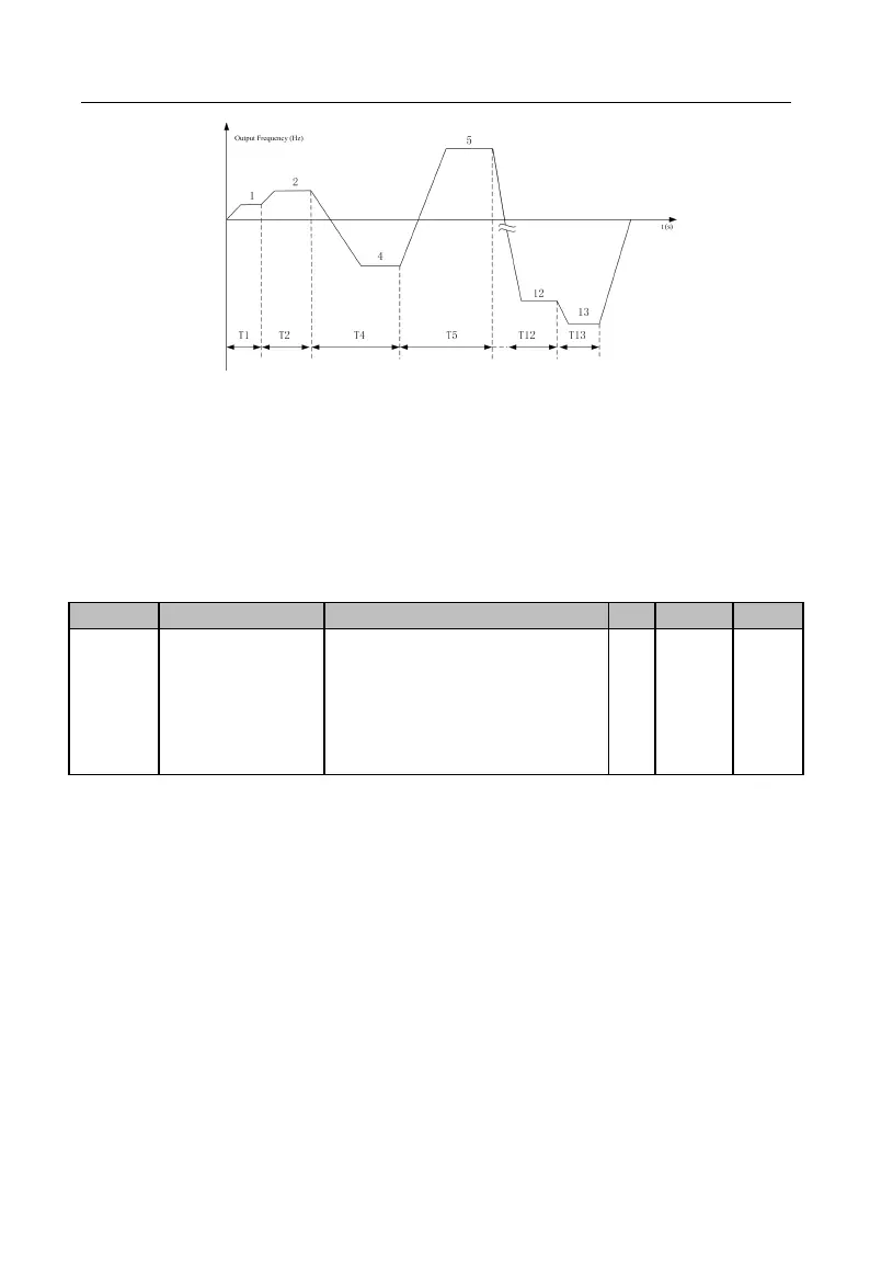
Figure 7-26 Simple PLC Running
As illustrated in Figure 7-26, it is the running mode after setting “0: Stop after
Single Running”. Since preset speed 3 is set as 0 (F08.24=0.0), inverter will not run at
preset speed 3 actually. Since preset speed 14 and preset speed 15 are set as 0
(F08.46=0.0 and F08.48=0.0), preset speed 13 is the last one and inverter will stop after
running at preset speed 13.
Ones Place: Stop Memory
0: Disabled (Start from Preset Speed 1)
1: Enabled (Start at Power Failure)
Tens Place: Power Failure Memory
0: Disabled (Start from Preset Speed 1)
1: Enabled (Start at Power Failure)
PLC stop memory function enables inverter to record the running times (F18.10),
running stage (F18.11) and present running time (F18.12) of present simple PLC at stop.
Inverter continues with the memorized stage for the running of the next time. If the
simple PLC memory function is disabled, the PLC process will be started for every time
after inverter restart.
PLC power failure memory function enables inverter to record the running times
(F18.10), running stage (F18.11) and present running time (F18.12) of present simple
PLC before the power failure. Inverter continues with the memorized stage at the next
energization. If the PLC power failure memory function is disabled, the PLC process will