EM500 Open-Loop Vector Control Inverter User Manual
259
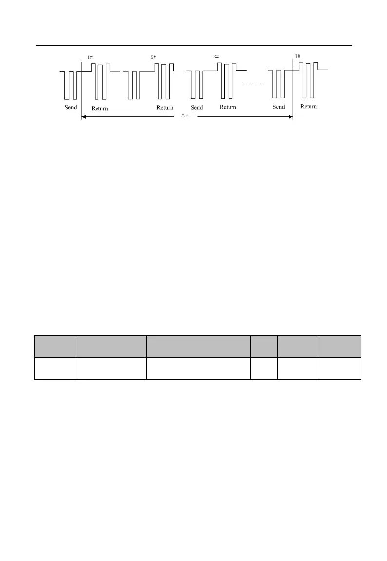
Figure 7-30 Communication Overtime
Application example: If master must send data to a slave (for example #1) within a
certain time T, then user may enable the communication overtime function for #1 slave
by setting F10.03>T. No fault report for the communication overtime will be triggered
during normal communication. However, if master does not send data to #1 slave for a
time period T and this condition is maintained for a time set by F10.03, then a
communication abnormality fault (E16) will be reported to notify the personnel of “#1
slave communication fault”, so that the personnel may conduct troubleshooting.
★ The time set by F10.03 must be greater than T, but must not be excessive,
otherwise the running of inverter under a fault condition for a long time may result in
adverse effects.
★F10.03 should be disable normally. Only in the continuous communication system,
set up the parameters, used to monitor the communication status.
Define the time interval from the receipt of valid data frame 1 by inverter, to data
learning, and then to starting the data return, as the response delay (t
w2
). To ensure that
the protocol chip works stably, the response delay shall be set as 1 ms to 20 ms (no 0). If
the communication data involves EEPROM, the actual response delay will be extended to
“EEPROM action time + F10.04”
1: valid data frame: sent by the external master to inverter, and the function code, data
length and CRC are correct.