EM500 Open-Loop Vector Control Inverter User Manual
49
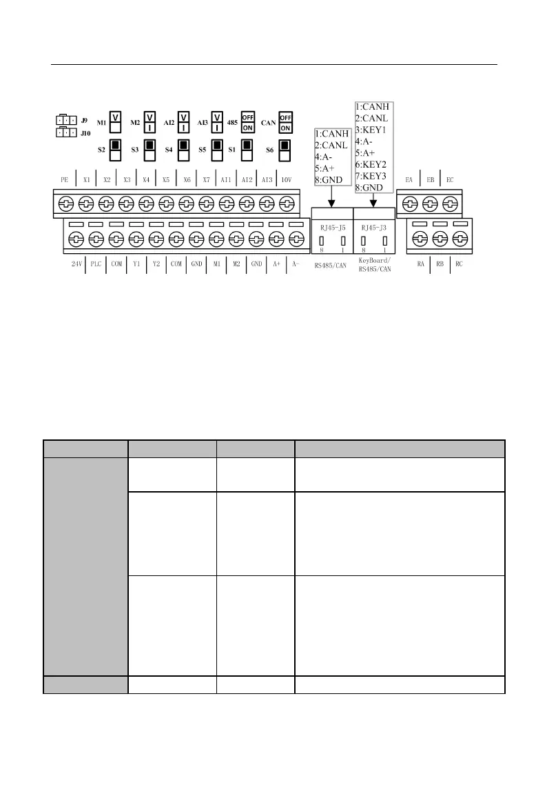
See Figure 3–12 for control circuit terminal block.
Figure 3-12 Control Circuit Terminal Block
Note: 1. Jump wires J9 and J10 of the terminal block are equipped by the
manufacturer. No user is allowed to change them, or else inverter may not work
normally. 2. S2 is VOID. M1 is analogy output ONLY for DC 0~10V.
3.3.2Function and Wiring of Control Circuit Terminals
See Table 3–5 for functions of control circuit terminals.
Table 3-5 Control Circuit Terminal Functions
Offers a +10V power supply, maximum
output current: 20mA.
Offers +24V power supply, generally used as
a working power supply for numeric input or
output terminal, or external device power
supply.
Maximum output current: 200mA.
Common
Multi-function
Input Terminal
As factory default, it is connected to 24 V
power supply.
When driving numeric input terminal with an
external power supply, disconnect it from 24V
terminal and connect it to external power
supply.
Input voltage range: DC 0 - 10 V