EM500 Open-Loop Vector Control Inverter User Manual
48
Please select the grounding wire of the specifications as stipulated in the
Technical Standards of Electrical Equipment and keep it as short as possible
when connecting to the ground point.
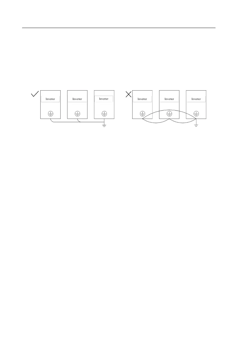
Do not allow the grounding cable to form a circuit when two or more
inverters are used. Correct and incorrect grounding methods are shown in
Figure 3–11.
Figure 3-11 Connection Methods of Grounding Cable
3.2.9 Braking Resistor and Braking Unit Wiring
See Chapter 11 for type selection and wiring methods of braking resistor and braking
unit.
3.3 Wiring Control Circuit Terminals
3.3.1Control Circuit Terminals
Control circuit terminals are located at the bottom front of terminal block and PCB
and comprise:
Analog input terminals: AI1, AI2 and AI3
Numeric input terminals: X1, X2, X3, X4, X5, X6 and X7
Numeric output terminals: Y1 and Y2
Relay output terminals: R1: EA-EB-EC, R2: RA-RB-RC
Analog output terminals: M1 and M2
Auxiliary power supply terminals: PLC, +24V, COM, +10V and GND
RS485 communication interface: A+ and A-
CANSinee interface:CANH and CANL
(optional)