EM500 Open-Loop Vector Control Inverter User Manual
157
(c) F00.03=1 (d) F04.19=0, F00.03=1
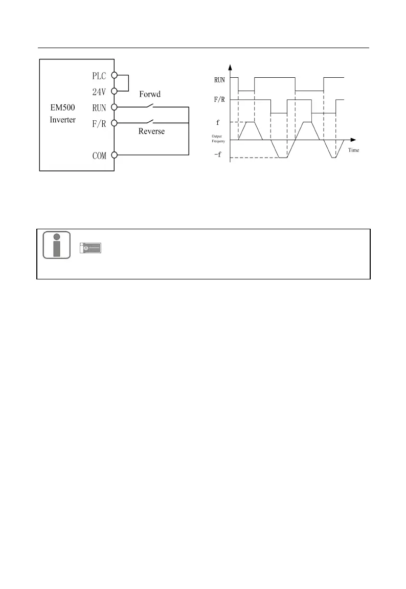
2-Wire Sequence Wiring Diagram Forward/Reverse Running Sequence
Figure 7-1 2-Wire Sequence
When selecting F00.03 start/stop option as 0 or 1, either pressing
or using an external terminal stop command can stop inverter,
even if terminal RUN is on. At this time, terminal RUN should be
disabled and then enabled, it can once again enter running state.
3-Wire Sequence:
F00.03=2: Terminal RUN forward, Xi stop, F/R reverse
RUN is a NO forward running button and F/R is a NO reverse running button; both
of them are effective at pulse edge; Xi is a NC stop button and enabled at the level. Under
running mode, pressing Xi can stop inverter. When stop mode is set as F04.19=0
Ramp-To-Stop, the logic diagram is shown in Figure 7-2 (b). Xi is a terminal among X1 -
X7 and defined as 3-Wire Sequence Run/Stop Control.
F00.03=3: Terminal RUN, Xi stop, Forward/Reverse (F/R)
RUN is a NO running button, and will be on at pulse edge (F/R is on at level). F/R is
a forward/reverse switching button (inverter forwards when F/R is disabled, and inverter
reverses when F/R is enabled). Xi is a NC stop button, and on at the level. When the stop
mode is set as F04.19=0 Ramp-To-Stop, the logic sequence is shown in Figure 7-2 (d).