EM500 Open-Loop Vector Control Inverter User Manual
192
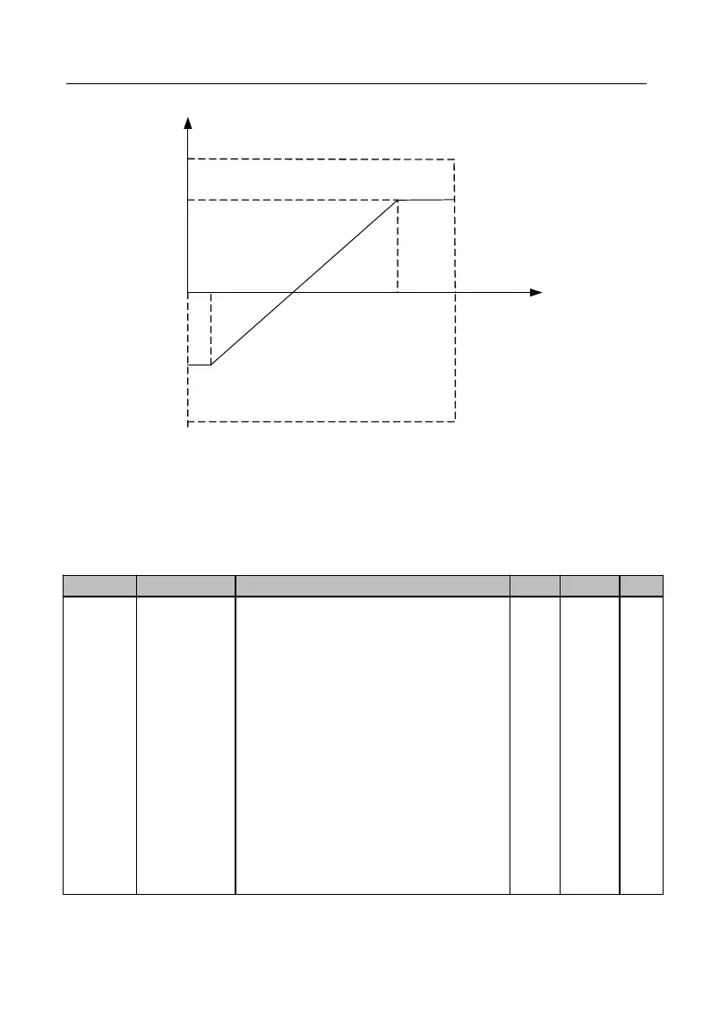
-100.0%
F02.29
F02.27
F02.26
F02.28
Offset
Output
Pulse Frequency/kHz
Figure 7-10 High-Speed Pulse Input Offset Curve
When input pulse frequency changes fast or the system does not need to make a
quick response to the input pulse, user may properly increase the filter time to stabilize
the system.
Ones Place: AI1
0: Analog Input
1: Numeric Input (0 for less than 1V,
1 for over 3V, contrary to the last
time for 1V-3V)
Tens Place: AI2
0: Analog Input
1: Numeric Input (the same as
above)
Hundreds Place: AI3
0: Analog Input
1: Numeric Input (the same as
above)
Thousands Place: AI4 (expansion
card)