EM500 Open-Loop Vector Control Inverter User Manual
191
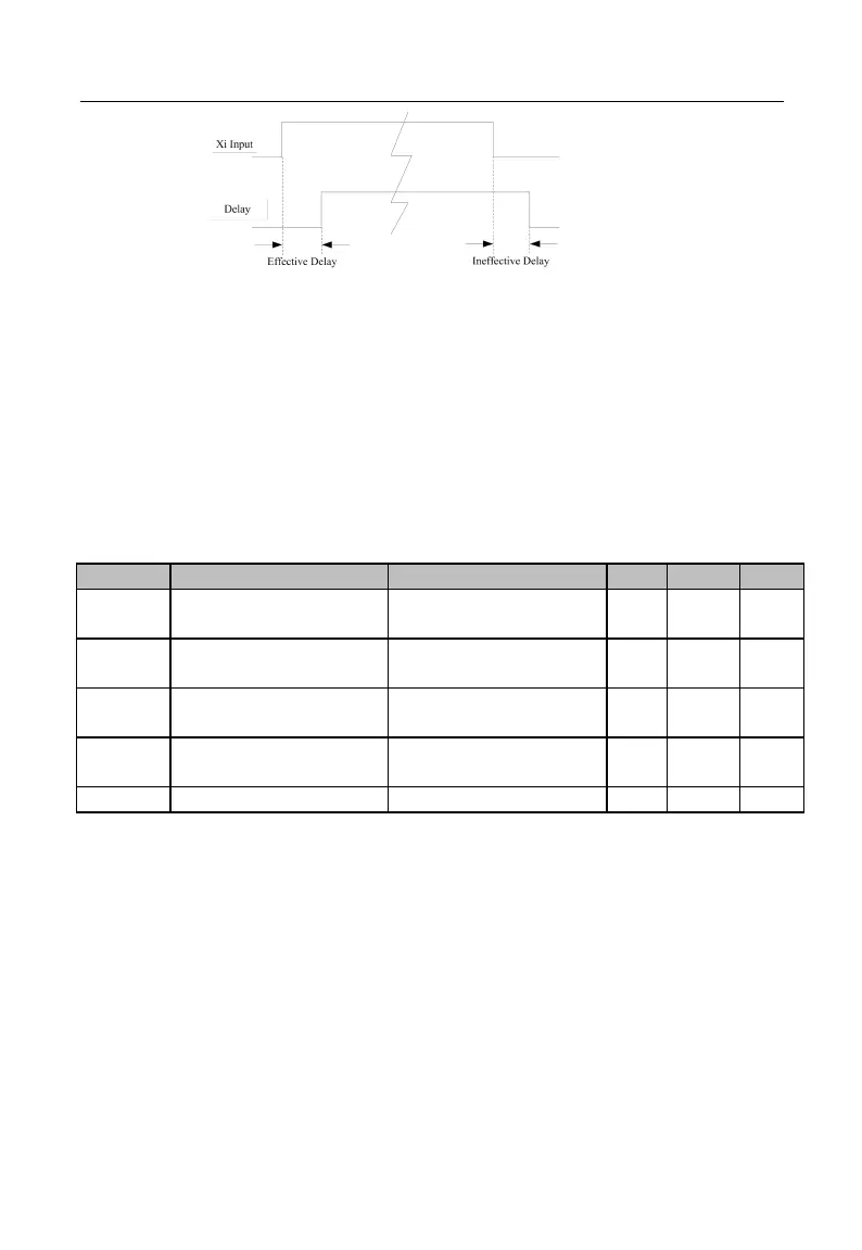
Figure 7-9 Terminal Delay Sampling
The terminal will delay to response according to the function code setting when the
function terminal status changes. At present, terminals X1 - X4 support this function.
Specific actions: this function will be active after the function terminal changes from
disabled status to enabled status and the effective delay time is reached; this function
terminal becomes inactive after the function terminal changes from enabled status to
disabled status and the ineffective delay time is reached.
★
If the function code is set as 0.000s, the delay is disabled accordingly.
Minimum Input Pulse
Frequency
0.00 - Maximum Input
Pulse Frequency F02.28
Setting Corresponding
to Minimum Input
Maximum Input Pulse
Frequency
Setting Corresponding
to Maximum Input
EM500 inverter supports high-speed pulse input (HDI) function, and terminal X7 is
shared. F02.26 - F02.30 are used to set the pulse filter time and corresponding offset
curve.
As indicated in Figure 7-10, the system realizes the line offset through the setting of
the two points (F02.26, F02.27) and (F02.28, F02.29) according to the input pulse
frequency size, and the input outside the frequency range will be cut off.