EM500 Open-Loop Vector Control Inverter User Manual
301
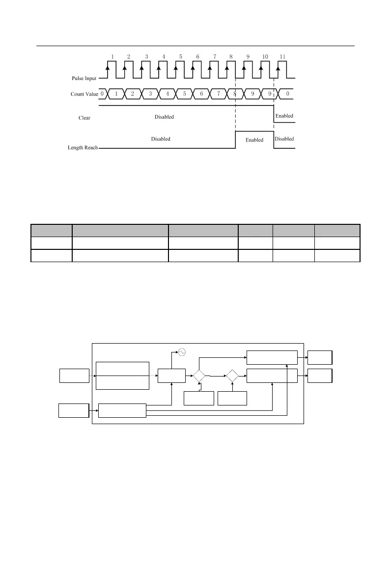
Figure 7-41 Fixed Length Count (Example)
When the length count reaches 8(=2×4), “16: Length Reach” is enabled; when “39:
Length Clear” is enabled, the count will be cleared and “16: Length Reach” output is
disabled.
EM500 inverter supports the count function (refer to Figure 7-42). The pulse
information is inputted via the numeric input terminal. When the count reaches a set
value, corresponding signal will be outputted. User may perform the programming with
this signal (for example input it via DI/VX to be used as a stop command). User may
view present count value via F18.33 in real time.
DO “Set Count Value Reach”
Output
(Function of No.14)
Pulse Count n
Cntin
DI “Counter Clear” Input
(Function of No.36)
Pulse Information
Count Clear Signal
Clear
Set Count Value
n2
(1 - 65535)
≥
Reset
DI “Count” Input
(Function of No.34)
HDI “Rapid Count” Input
(Function of No.35)
Designated
Count Value
Reach Signal
Comparer 2
F18.33
≥
Designated Count
Value n1
(1 - 65535)
Comparer 1
DO “Designated Count Value
Reach” Output
(Function of No.15)
≤
≤
0
Designated
Count Value
Reach Signal
Figure 7-42 Block Diagram of Count Function
Principle of work: When certain information is inputted in the form of pulse. DI
terminal collects the information about the input pulse number
, and then compare it