EM500 Open-Loop Vector Control Inverter User Manual
196
User may properly increase the function code, if the input fluctuates greatly due to
analog input hysteresis, long input line or severe field interference. The principle of
adjustment is to reduce the adjustment as possible
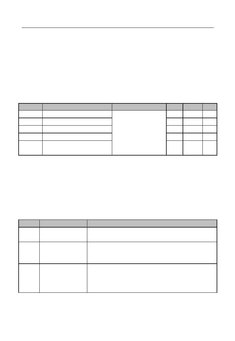
7.4 F03 Group: Output Terminal Function Parameter
EM500 inverter has 2 multi-functional input terminals (Y1 and Y2) and 2 relay
output terminals (R1 and R2). In addition, IO expansion card (EC-IO-A1, see Appendix I)
is optional and offers 1 multi-functional input output terminals (Y3).
See Table 7–6
Functions of Numeric
Multi-Function Input
Terminals
Y3 Output Function
(Expansion Card)
Y1 – Y3, R1 and R2 are 5 numeric multi-function output terminals. By setting the
function codes F03.00 - F03.04, user may define the functions of output terminals
respectively.
For example, if F03.02=7, the function of terminal R1 is “inverter fault”. If inverter
is in the fault status, R1 is in active output status; if inverter is normal status, R1 is in
inactive output status. Specific functions available are shown in Table 7-6.
Table 7–6 Numeric Multi-Function Output Terminals
Set “0: No Function” for an unused or fault terminal to
prevent false output.
When inverter is in slave running, slave stop, JOG running
or JOG stop status, present output is active; in other status,
present output is inactive.
Frequency Reach
Range (FAR)
When inverter is in running status and the absolute value of
“output frequency – the set frequency” ≤ frequency reach
detection width (F15.20), present output is active; when
inverter is not in running status or the absolute value of