EM500 Open-Loop Vector Control Inverter User Manual
53
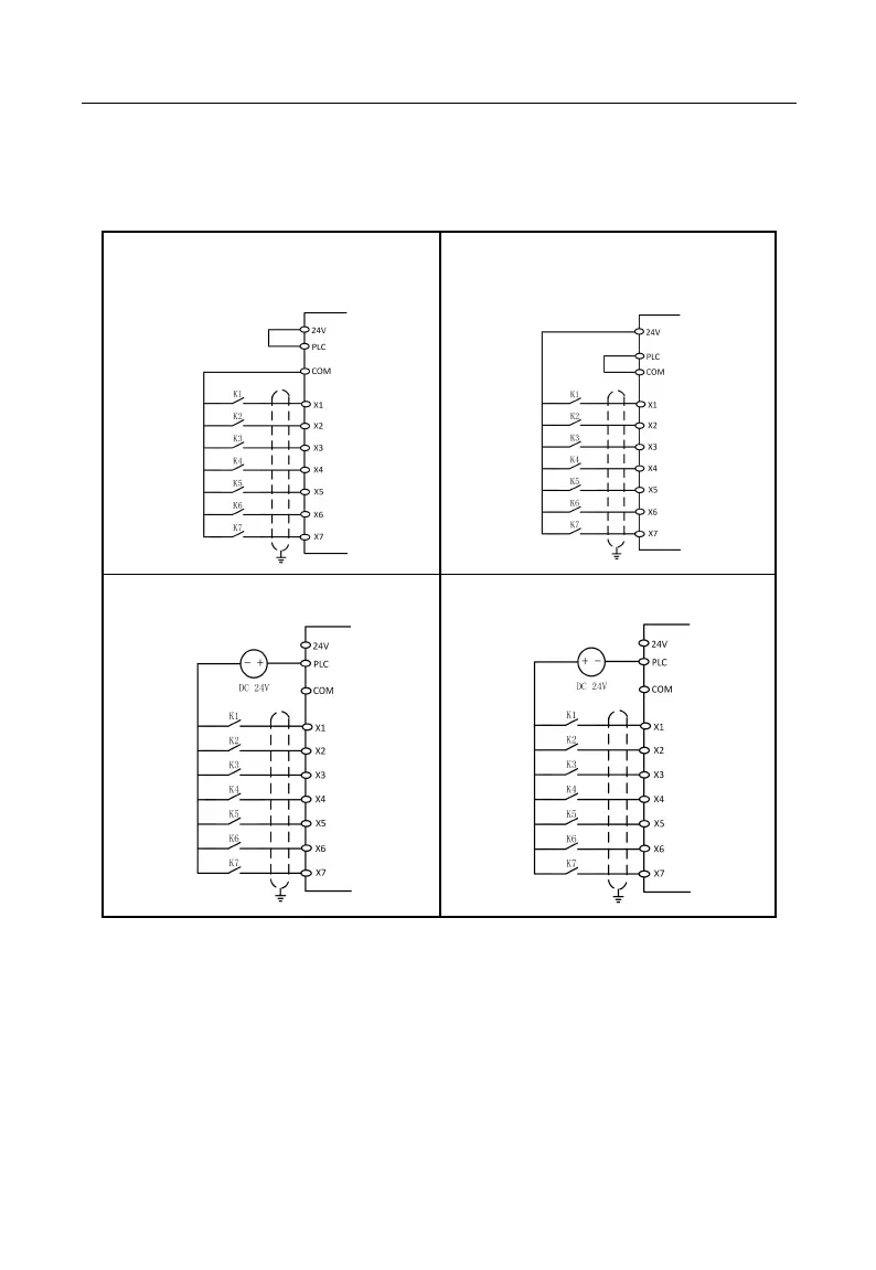
be either forward (NPN Mode) or reverse (PNP Mode), so that it is flexible to connect
terminals X1 - X7 to external devices. Typical wiring methods are shown in the
following:
A. NPN mode with internal power supply
(+24Vdc)
B. PNP mode with external power supply
(+24Vdc)
C. NPN mode with external power supply
D. PNP mode with external power supply
Figure 3-17 Wiring of Multi-function Input Terminals
Note: Wiring of relay output terminal of the short-circuiting bar between 24V power
supply and PLC terminal must be removed, before using an external power supply.
Absorption circuit of surge voltage should be installed to drive the inductive load
(for example relay and contactor), for example RC absorption circuit (please note that the