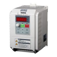
Do you have a question about the Sinee A90-2T4R8B and is the answer not in the manual?
General safety guidelines for installation, operation, and maintenance to prevent hazards.
Details on inverter models, voltage ratings, applicable motors, and output current specifications.
Explanation of inverter working states: parameter setting, normal running, jog, stop, and fault statuses.
Steps to verify product condition and order consistency upon receipt.
Specifies environmental conditions, ventilation, temperature, and site preparation for installation.
Guidance on inverter orientation and clearance for proper heat dissipation.
Standard wiring diagram showing connections between the inverter and peripheral devices.
Details the layout and function of main circuit terminals for power input/output and grounding.
Explains control circuit terminals for input, output, and communication connections.
Overview of the LED keyboard's structure, keys, displays, and status indicators for operation.
Describes keyboard operation modes: monitoring, menu selection, function code, and parameter levels.
Step-by-step guide for initial inverter startup, configuration, and testing.
Crucial checks for wiring, grounding, and load status before energizing the inverter.
Methods for controlling inverter start and stop operations via keyboard, terminals, or communication.
Explains the organization of function codes into groups and their general purpose.
Comprehensive listing of all functional parameters, their settings, units, and attributes.
Details core function codes for drive modes, command sources, terminal control, and frequency sources.
Explains the process of automatically measuring motor parameters for improved control accuracy.
Important considerations and steps to take before performing motor parameter self-identification.
Step-by-step guide for performing static and rotary self-identification for different motor types.
Lists fault codes, their causes, and recommended solutions for inverter abnormal statuses.
Analyzes common operational failures like incorrect parameter settings and abnormal motor rotation.
Routine inspection and cleaning procedures for the inverter to ensure proper operation and prevent faults.
Details warranty terms and conditions for inverter body, and fees for out-of-warranty services.
Explains the function of braking resistors for regenerative energy and provides selection guidance.
Introduces the BR100 series braking units and their power ranges for A90 inverters.
Specifies wire requirements for braking units and resistors, including insulation and cross-section.
Defines the series and network types supported by the A90 inverter for MODBUS-RTU communication.
Details the RS-485 communication mode, network address, data format, and baud rate settings.
Explains the structure of MODBUS RTU messages, including PDU, CRC check, and function codes.
Defines communication timeout intervals based on baud rate and idle time for reliable data transmission.
| Model | A90-2T4R8B |
|---|---|
| Category | Inverter |
| Output Waveform | Modified Sine Wave |
| Input Voltage | 12V DC |
| Output Voltage | 220V AC |
| Output Frequency | 50Hz |
| USB Output | 5V/2.1A |
| Cooling | Fan |
| Protection | Overload, Short Circuit |


 Loading...