User Manual of A90 Series Inverter
271
Chapter 12 MODBUS Communication Protocol
12.1 Applicable Scope
1.
Applicable series: A90 series
2.
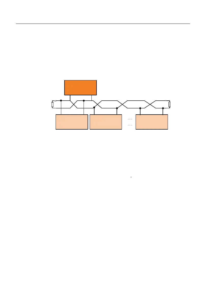
Applicable network: Support the “single-master multi-slave” communication
network with MODBUS-RTU protocol and RS-485 bus.
A+A-
Host
A+A-
Inverter 1#
A+A-
Inverter 2#
A+A-
Inverter n#
A-
A+
12.2 Interface Mode
RS-485 asynchronous half-duplex communication mode, with the least significant bit
sent first;
RS-485 network address: 1-247; 0 is the broadcast address;
Default data format of RS-485 terminal: 1-8-N-1
[
2
]
(options: 1-8-E-1, 1-8-O-1,
1-8-N-2, 1-8-E-2 and 1-8-O-2);
Default baud rate of RS-485 terminal: 9600bps (options: 4,800bps, 19,200bps,
38,400bps, 57,600bps and 115,200bps)
It is recommended to use twisted-pair shielded cable as the communication cable to
reduce the impact of external interference on communication.
[2]: 1-8-N-1, meaning 1 start bit - 8 characters per byte of data - no parity - 1 stop bit.
E: even parity. O: odd parity.
12.3 Protocol Format
12.3.1 Message format
As shown in Fig. 0-1, a standard MODBUS message includes a start tag, RTU
 Loading...