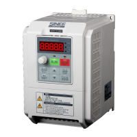
Do you have a question about the Sinee A90-4T017B and is the answer not in the manual?
Covers critical safety measures for installation and wiring to prevent hazards.
Outlines essential safety checks and actions before and after powering the inverter.
Details safety guidelines for operating the inverter and performing maintenance.
Addresses motor insulation, thermal protection, and operational factors like altitude.
Details the inverter models, voltage ratings, applicable motors, and output currents.
Explains various inverter working statuses and operational control modes.
Instructions on checking the product for completeness and potential damage upon receipt.
Provides physical dimensions and mounting details for installation.
Specifies environmental conditions and site requirements for proper inverter installation.
Details the correct installation orientation and necessary clearance for heat dissipation.
Illustrates the standard connection scheme between the inverter and peripheral devices.
Explains the composition and layout of main circuit terminals for proper wiring.
Details the composition and functions of control circuit terminals for wiring.
Describes the structure of the LED keyboard and the functions of its keys and indicators.
Explains the different operation modes and menu selection processes.
Outlines the step-by-step procedure for commissioning the inverter.
Lists essential items to confirm before turning on the inverter's power supply.
Details how to control the inverter's start and stop operations using various methods.
Explains the organization and meaning of function code groups and parameters.
Lists all functional parameters with their descriptions, default settings, and attributes.
Details basic function parameters for command source, terminal control, and frequency sources.
Specifies parameters for motor 1, including type, power, voltage, current, and winding connection.
Explains the configuration and functions of digital and analog input terminals.
Details the functions and output types of multi-function digital and relay output terminals.
Covers parameters for start-up methods, DC braking, and speed tracking during start.
Details parameters for V/F curve settings, voltage sources, and compensation gains.
Explains parameters for speed and torque control, flux weakening, and SVC.
Details parameters for protection settings like overload, overvoltage, undervoltage, and load loss.
Covers parameters for setting multiple speed segments and simple PLC operation modes.
Details parameters for PID control, including setting sources, gains, and switching conditions.
Explains Modbus communication settings like address, baud rate, data format, and timeouts.
Allows users to select and configure specific function codes for quick access.
Covers parameters related to keyboard functions, display modes, and parameter locking.
Details parameters for controlling motor torque, including setting sources and limits.
Specifies parameters for a second motor, allowing separate configuration.
Covers auxiliary functions like jog control, acceleration/deceleration switching, and frequency hopping.
Defines functions for virtual input and output terminals for flexible configuration.
Allows viewing of current inverter status like output frequency, current, voltage, and bus voltage.
Records and displays information about the last three faults, including type and status.
Explains the process of automatically measuring motor parameters for optimal control.
Lists critical precautions to ensure proper and safe motor parameter self-identification.
Provides a step-by-step guide for performing motor parameter self-identification.
Lists fault codes, their causes, and corresponding solutions for troubleshooting.
Provides analysis and solutions for common inverter failures and motor rotation abnormalities.
Details routine inspection and cleaning tasks for the inverter during operation and storage.
Outlines the warranty coverage, service terms, and conditions for inverter repairs.
Explains the purpose of braking resistors and how to calculate their power and resistance.
Lists models of available braking units and their specifications for A90 series inverters.
Defines the series and network types supported by MODBUS communication.
Describes the RS-485 asynchronous half-duplex communication mode and default settings.
Details the structure of MODBUS RTU messages, including header, PDU, and CRC.
Classifies MODBUS function codes into common and user-defined types for various operations.


 Loading...