User Manual
EM303A General Purpose Inverter
79
No. Function Range Unit Default Type
F0-04 Start/Stop Control Options
0: Keypad
1: Terminal
2: RS485
0 〇
F0-05
Terminal Start/Stop
Control Options
0:RUN-Run,
F/R-Forward/Reverse
1: RUN- Forward,F/R-
Reverse
2: RUN-NO forward,
Xi-NC stop,
F/R-NO reverse
3: RUN-NO run, Xi-NC stop,
F/R- Forward/Reverse
0 〇
F0-04=0 Keypad Control Mode:
Control start/stop of inverter through RUN,
STOP/RESET, JOG/+- buttons on the keypad.
When there is no fault, press JOG/+- to enter jog
status, and RUN to enter running status. When the
green LED indicator on the RUN button is on, the
inverter is in running status, but when it flashes, the
inverter is in ramp-to-stop status. No matter the
setting input control mode is speed or torque, JOG
is always running in jog speed input control mode.
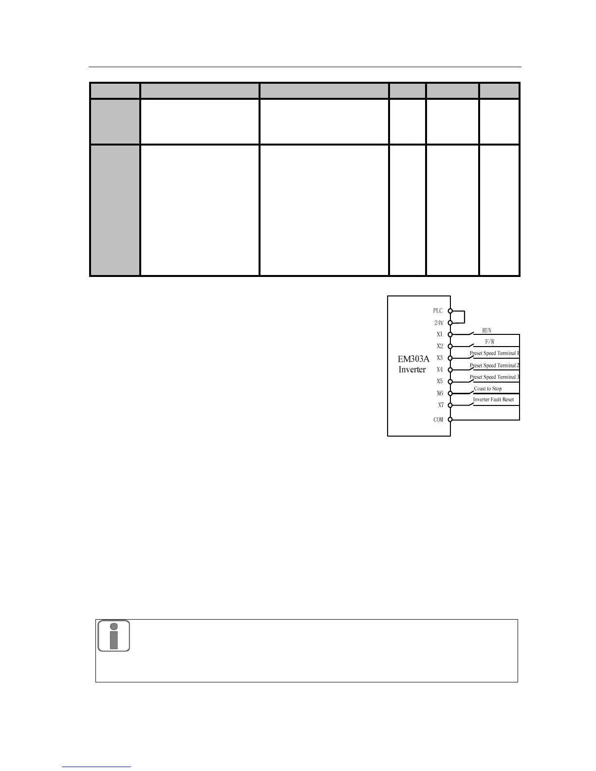
F0-04=1 Terminal Control Mode:
Start/Stop of inverter controlled by Start/Stop
control terminals defined by F2
-00~F2-06. When
multi-function terminals are set as defaults, the terminal control wiring is as shown
in Figure 7-1.
Specific setting of terminal control is determined by F0
-05.
F0-04=2 RS485 Control Mode:
Start/Stop of inverter is under PC or PLC control through RS485 communication
interface.
1. The terminal set as JOG can control inverter to run in jog speed setting
mode in all start/stop modes.
2. No matter in what drive control mode, JOG always runs in jog speed setting control
mode.
Figure 7-1 Wiring of Terminal
Control
 Loading...

