EasyManua.ls Logo

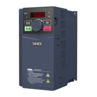
Sinee EM730/EM730E-1R5-3B User Manual

Sinee EM730/EM730E-1R5-3B
345 pages
To Next Page IconTo Next Page
Page #1 background imageLoading...
Page #1 background image
User Manual of EM730/EM730E Series Inverter
1
Preface
Thank you for choosing SINEE’s EM730/EM730E series inverter.
Document No.:
31010183
Release time:
June 2020
Version:
100
The EM730/EM730E series inverter is a high-reliable and small-sized universal inverter
launched by SINEE. EM730 supports three-phase AC asynchronous motors, while EM730E
supports permanent magnet synchronous motors. They support a variety of drive control
technologies, such as the vector VF (VVF) control and speed sensorless vector control (SVC);
speed output and torque output; and Wi-Fi access and background software debugging.
Features of the EM730/EM730E series inverter:
Support debugging by the mobile phone APP or monitoring of the inverter status;
Support Wi-Fi module or serial port access;
Rich and convenient PC background software functions;
No need for derating at the ambient temperature of 50 ;
Support “one-key shuttle” for fast and accurate speed adjustment;
Perfect protections: Protections against the short circuit, overcurrent, overvoltage,
overload, overheating, etc.
Before using the EM730/EM730E series inverter, please read this manual carefully
and keep it properly.
While connecting the inverter to motor for the first time, please select the motor type
(asynchronous or synchronous) correctly and set the motor nameplate parameters:
rated
power, rated voltage, rated current, rated frequency, rated speed, motor connection, rated
power factor, etc.
Since we are committed to continuously improving our products and product data, the data
provided by us may be modified without prior notice.
For the latest changes and contents, please visit www.sinee.cn.

Table of Contents

Question and Answer IconNeed help?

Do you have a question about the Sinee EM730/EM730E-1R5-3B and is the answer not in the manual?

Sinee EM730/EM730E-1R5-3B Specifications

General IconGeneral
Nominal AC Voltage230V
Max. Input Current30A
Efficiency96.5%
Output Voltage230V
Output Frequency50Hz/60Hz
Protection FeaturesOver Temperature

Summary

Safety precautions

Before installation

Safety measures to take before installing the inverter.

During installation

Safety measures to take during the installation process.

During wiring

Safety measures to take during the wiring process.

Before power-on

Safety checks and precautions before powering on the inverter.

After power-on

Safety guidelines to follow after the inverter is powered on.

During operation

Safety precautions to observe while the inverter is in operation.

During maintenance

Safety guidelines for performing maintenance on the inverter.

Chapter 2 Installation

2.1 Product check

Procedures for verifying the product upon receipt and before installation.

2.3 Installation Site Requirements and Management

Specifies the necessary conditions for the installation site and management practices.

Chapter 3 Wiring

3.1 Connection of Peripheral Device

Illustrates the standard connection of the inverter with peripheral devices.

3.2 Wiring of Main Circuit Terminal

Details the composition and layout of the main circuit terminals.

3.2.4 Input side wiring of main circuit

Covers the installation of circuit breakers, leakage circuit breakers, and electromagnetic contactors.

3.2.5 Output side wiring of main circuit

Details wiring instructions for the output side, connecting the inverter to the motor.

3.2.7 Ground wire

Provides instructions and best practices for grounding the inverter.

3.3 Wiring of Control Circuit Terminal

Details the composition and functions of the control circuit terminals.

3.3.9 Precautions for control circuit wiring

Provides essential precautions for wiring the control circuit to prevent interference and ensure proper function.

3.5 Connection test

Checks to perform after wiring to ensure correctness and safety.

Chapter 4 KEYBOARD OPERATIONS

4.1 Keyboard Functions

Overview of the LED keyboard structure and its components.

4.2 Operation Mode of Keyboard with Digital Tube Display

Explains the menu structure and navigation modes of the keyboard display.

4.3 Protection Monitoring

How to monitor protection status and related parameters.

4.4 Operation Monitoring

How to view operational parameters and status information.

4.5 Run/Stop

How to start and stop the inverter using the keyboard.

Chapter 5 Trial run

5.1 Inverter Commissioning Process

Outlines the steps involved in commissioning the inverter.

5.2 Confirmation before Power-on

Crucial checks to perform before applying power to the inverter and motor.

5.7 Motor Parameter Identification

Explains the process of identifying motor parameters for optimal control performance.

Chapter 7 Function Code Details

7.8 F07 protection parameter group

Configuration of various protection and warning functions.

Related product manuals