30
At least once a year thereafter, these grease cups
should
be removed
and refilled with the Singer Motor Lubricant,
fur—
nished
With the
machine. To do this, the motor
must be
removed
from the machine.
3. To remove the
motor:
(a) Remove the motor cover (C,
Fig. 5, page 5).
(b) Remove the two screws (K3, Fig. 24, page 27) which
hold
the motor.
(c) the entire motor (See Fig. 11,
page 12)
from
the machine by turning it
slightly
from side
to side
and at the same time pulling
it toward you.
The
motor
should only be withdrawn far enough to expose
the
two grease cups Fig. 11). Do not disconnect
any
of the electric wiring of the machine or the
motor).
(d) Unscrew the two grease cups (QQ,
Fig.
11).
(e) Fill the grease cups with Singer Motor Lubricant
(not
oil)
Without removing the wicks from the grease
cups.
(f) Fill the well in which the spiral pinion
(U,
Fig.
12,
page 12) revolves, with Singer Motor
Lubricant
(not
oil) .
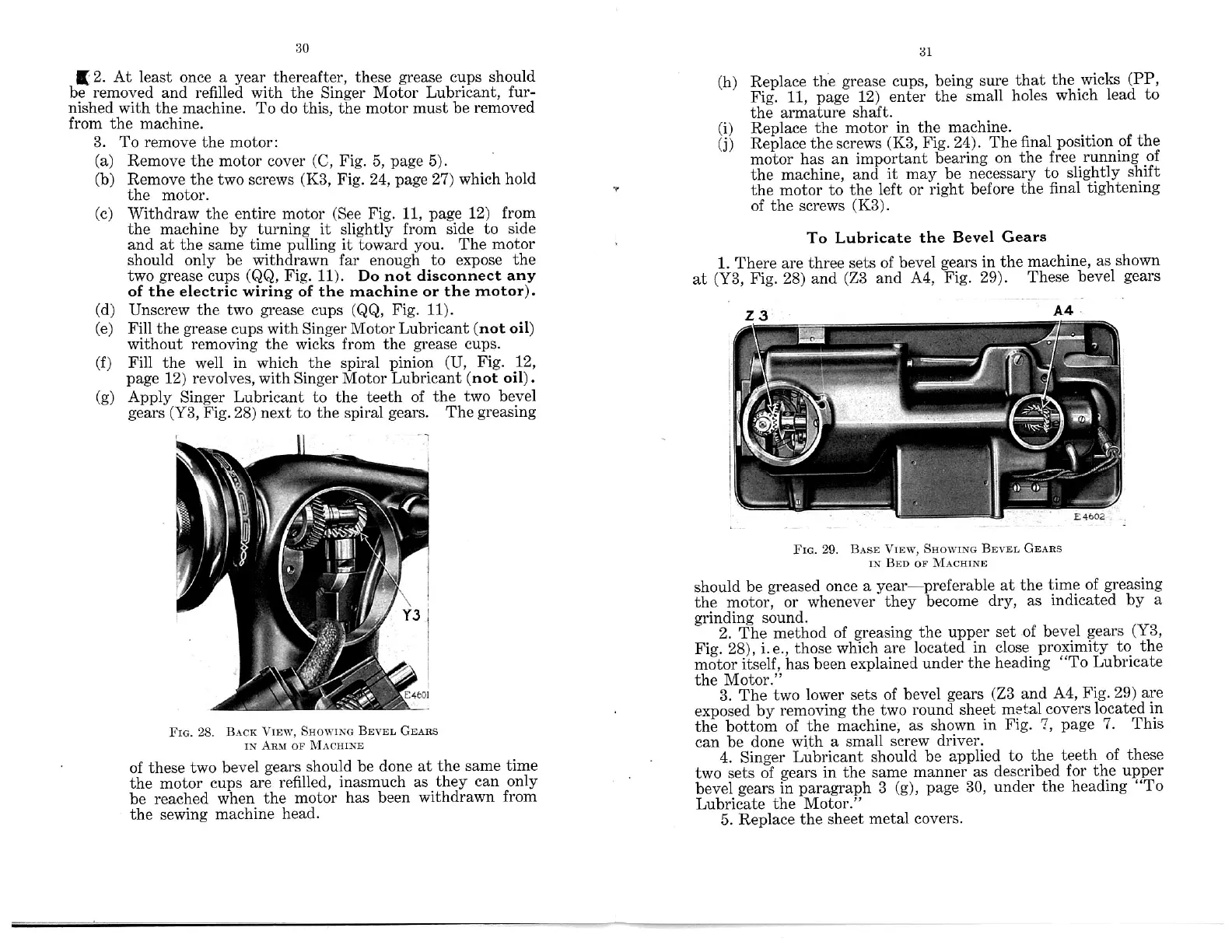
(g) Apply Singer Lubricant to the
teeth of the
two bevel
gears (Y3, Fig. 28) next to the spiral gears.
The
greasing
FIG.
28.
BACK
BEVEL
GEARS
IN
OF
of
these
two bevel
gears
should
be done
at the same
time
the motor
cups
are
refilled,
inasmuch
as
they can
only
be
reached
when
the motor
has been
withdrawn
from
the sewing
machine
head.
(h)
Replace
the grease
cups,
being sure
that
the wicks
(PP,
Fig. 11,
page 12)
enter the
small
holes
which
lead
to
the armature
shaft.
(i)
Replace
the motor
in the
machine.
(j)
Replace
the
screws (K3,
Fig.
24). The
final
position
of the
motor has
an important
bearing
on
the
free
running
of
the machine,
and it
may be
necessary
to slightly
shift
the
motor
to the
left or right
before
the
final
tightening
of the
screws
(K3).
To
Lubricate
the Bevel
Gears
1. There
are three
sets of
bevel gears
in
the machine,
as shown
at (Y3,
Fig. 28)
and (Z3 and
A4, Fig.
29).
These
bevel
gears
FIG.
29.
VIEW,
BEVEL GEARS
iN BED OF
should
be greased
once
a year—preferable
at the
time
of greasing
the
motor,
or whenever
they
become
dry,
as indicated
by a
grinding
sound.
2. The method
of
greasing
the upper
set
of bevel
gears
(Y3,
Fig. 28),
i.e., those
which
are located
in
close
proximity
to
the
motor
itself,
has been
explained
under
the heading
“To Lubricate
the Motor.”
3.
The two
lower
sets of
bevel
gears (Z3
and A4,
Fig.
29)
are
exposed
by removing
the
two round
sheet
metal
covers
located
in
the bottom
of
the machine,
as shown
in
Fig. 7,
page
7. This
can
be done
with
a small
screw
driver.
4. Singer
Lubricant
should
be applied
to
the
teeth
of these
two sets
of gears in
the same
manner
as
described
for
the upper
bevel
gears in
paragraph 3
(g), page
30,
under
the
heading
“To
Lubricate
the Motor.”
5. Replace
the
sheet
metal covers.
(2.
Withdraw.
(QQ,
y
x
VIEW,
SHOWING
AR.“
MACHINE
31
BASE SIIOWING
MACHINE


 To Next Page
 Loading...