EasyManua.ls Logo

Singer 101 Series - Page 18

Singer 101 Series
20 pages
Print Icon
To Next Page IconTo Next Page
To Previous Page IconTo Previous Page
Loading...
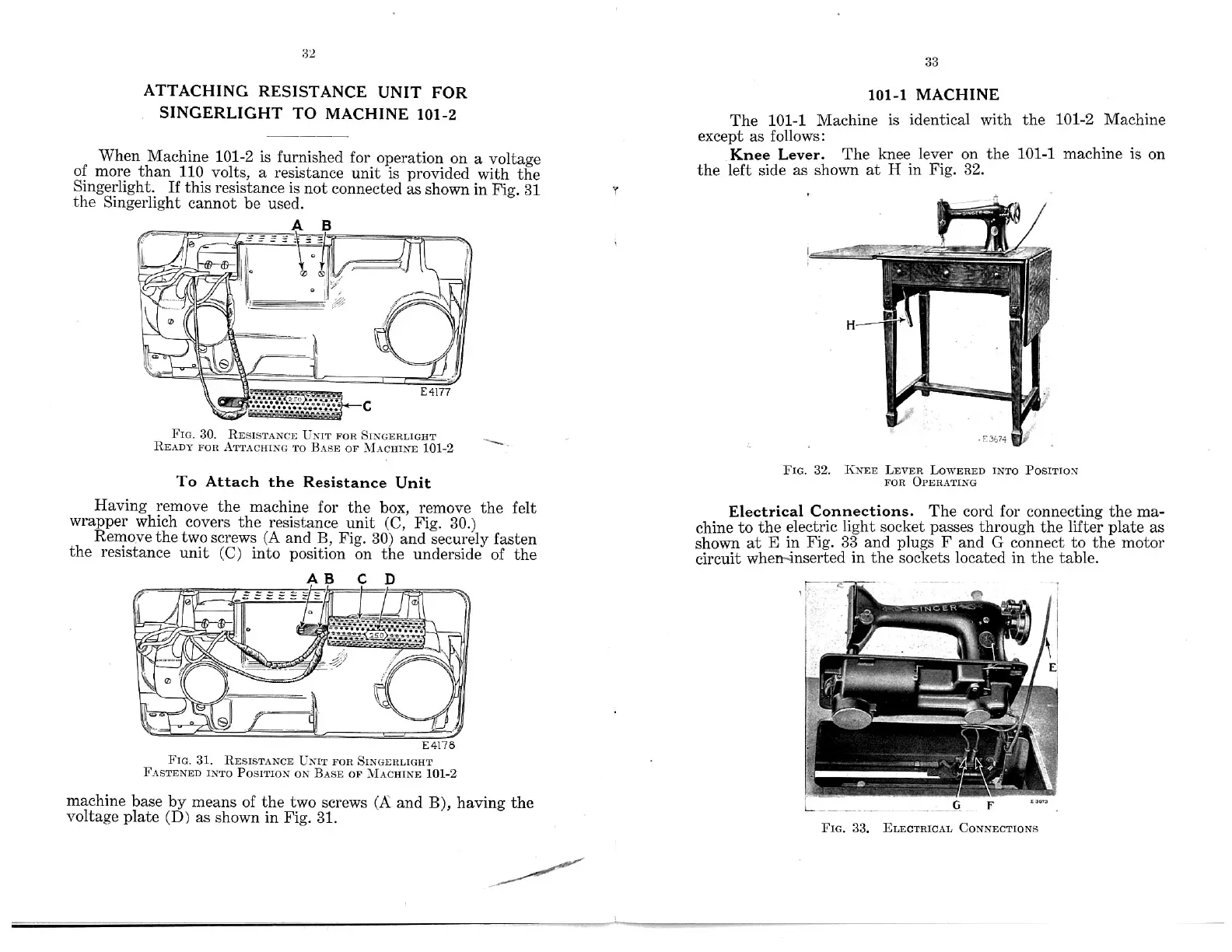
ATTACHING
RESISTANCE
UNIT
FOR
SINGERLIGI—IT
TO
MACHINE
101-2
When
Machine
101-2
is furnished
for operation
on a
voltage
of
more
than
110 volts,
a
resistance
unit
is provided
with
the
Singerlight.
If this
resistance
is not connected
as shown
in
Fig. 31
the
Singerlight
cannot
be
used.
FIG.
30.
FOR
FOR
To
101-2
To Attach
the Resistance
Unit
Having
remove
the
machine
for
the box,
remove
the felt
wrapper
which
covers
the
resistance
unit
(C, Fig.
30.)
Remove
the two
screws
(A
and B, Fig.
30) and
securely
fasten
the
resistance
unit
(G)
into position
on
the underside
of
the
FIG.
31.
UNIT
FOR
INTO
POSITION ON
BASE OF
101-2
machine
base
by means
of
the two screws
(A and B),
having the
voltage
plate
(D) as shown
in Fig. 31.
33
101-1
MACHINE
The
101-1
Machine
is identical with the 101-2 Machine
except
as follows:
Knee Lever.
The knee
lever on
the 101-1 machine is
on
the left side
as shown
at H in
Fig. 32.
FIG.
32. KNEE LEVER
LOWERED INTO
FOR OPERATING
Electrical
Connections. The cord
for connecting the ma-
chine
to
the
electric light socket passes through
the lifter plate as
shown
at E
in
Fig. 33 and plugs F and
G connect to the motor
circuit
in the sockets located
in the table.
FIG.
33.
CONNECTIONs
32
E4177
RESISTANCE
I'NIT
SINGERLIGHT
_
\
READY
A’I‘TACIIING
BASE
or MACHINE
E4178
RESISTANCE
SINGERLIGHT
FASTENED
MACHINE
POSITION
when~inserted
ELECTRICAL