10
Speed of Machine Too
a higher voltage than that stamped on the name plate,
the speed
of the machine will be too fast.
3. When the motor
is used on alternating current, see
if the
number of
cycles
of the circuit corresponds with that stamped
on the motor name plate. A 60 cycle motor will run too
fast
on a 50 cycle circuit.
Motor Fails to
Run
This may be due to any one of the following reasons:
1. Loose
or broken connections.
2. Observe carefully all plugs and connections and make sure
that there are no broken wires and that all screwed connections
are tight. ‘
3. Electric current not
turned on.
4. See that the voltage and number of cycles of the circuit
corresponds with that stamped
on the motor name plate.
5. Round-head brass screw in terminal plate hole (either
A
or D) not making good contact. The screw may be loose or the
threads on the screw may be stripped.
6. Carbon brushes (W, Fig. 13, page 13) not making contact
due to sticking in brush tubes or on account of grease on the
commutator.
7. Controller circuit open. Note whether the contact finger
(T3, Fig. 10, page 11_‘. makes good contact on the various buttons
of the
controller.
Turn the balance
wheel
slowly over toward you by hand to
ascertain if there is any excessive friction or binding in the machine.
Remove the motor from the machine, as instructed on pages
12 and 13, and see if armature turns over freely by running the
finger over the spiral pinion (U, Fig. 12, page 12). If the armature
turns stiffly, it should be adjusted to turn freely by following
the instructions given on page
Excessive friction in the motor may be due to any
of the
following reasons:
1. Spiral pinion (U, Fig. 12, page 12) on motor
shaft not
properly adjusted.
2. No lubricant in grease cups (Q, Fig. 11, page 12).
3. Lubricating wicks (P, Fig. 11, page 12)
not touching motor
shaft.
4. Brush tubes (V, Fig. 13, page 13) rubbing on commutator.
5. Armature striking field coils.
1]
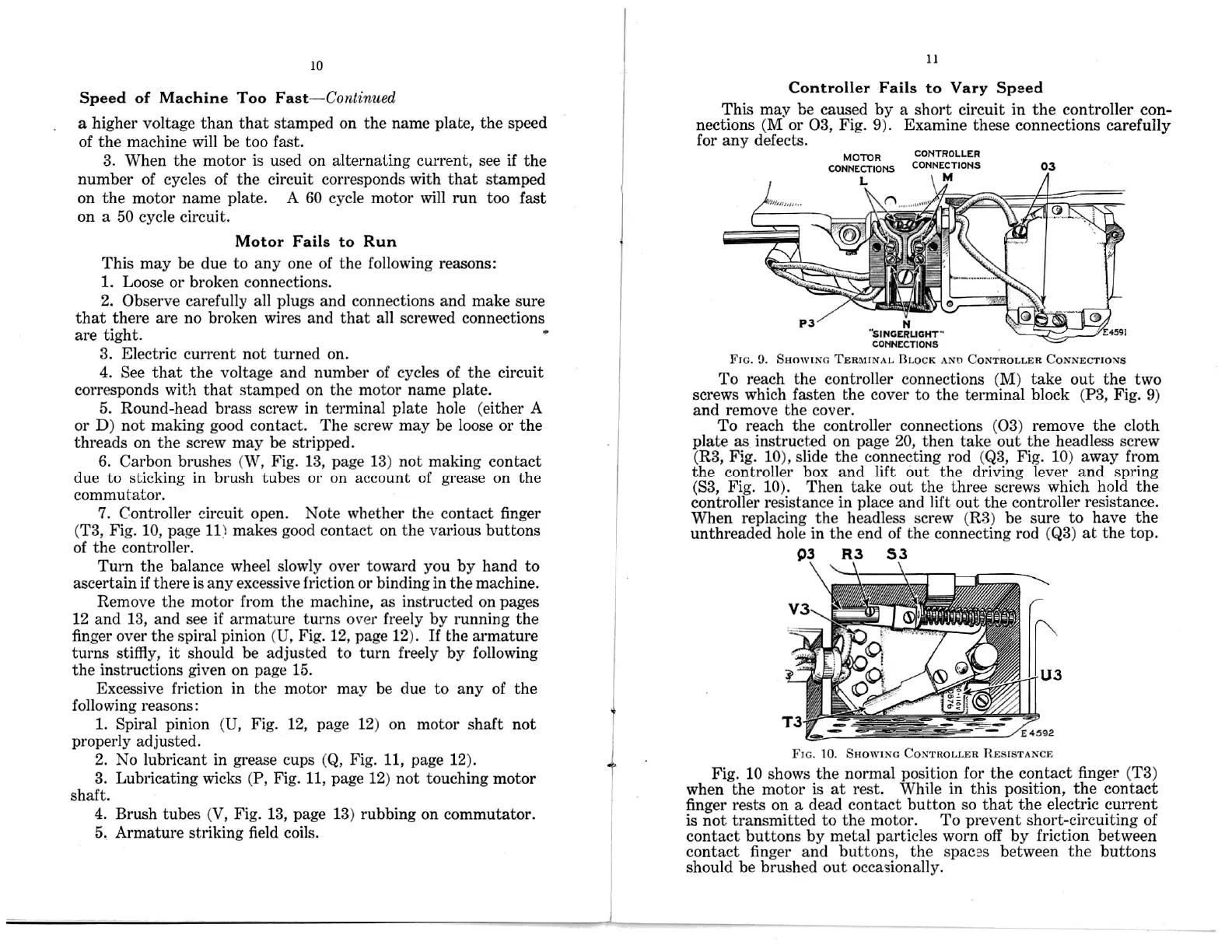
Controller
Fails to Vary Speed
This may be caused by a short circuit in the controller
con-
nections (M
or 03, Fig. 9). Examine these connections carefully
for any
defects.
CONTROLLER
CONNECTIONS
M
M
R
CONNECTIONS
N
FIG.
SHOWING TERMINAL BLOCK AND
To reach the controller connections (M) take out the two
screws which fasten the cover to the terminal block (P3, Fig. 9)
and remove the cover.
To reach
the controller connections (03) remove the cloth
plate as on page 20, then take out the headless
screw
(R3, Fig. 10), slide the connecting rod
(Q3,
Fig. 10) away
from
the controller box and lift out the driving lever
and spring
(S3, Fig. 10). Then take out the three
screws
which
hold the
controller resistance in place and lift out the controller
resistance.
When replacing
the headless screw (R3) be sure to
have the
unthreaded
hole in the end of the connecting
rod (Q3) at the
top.
FIG. 10. SHOWING
Fig. 10 shows the normal
position for the contact
finger (T3)
when the motor is
at rest. While in this
position, the contact
finger rests
on a dead contact button so
that the electric
current
is not transmitted to the
motor. To prevent short-circuiting of
contact buttons by metal
particles worn off by friction between
contact finger
and buttons, the spaces between the buttons
should be brushed out occasionally.
Fast—Continued
15.
03
OTO
s— ‘ ,
"smcmuom'"
4591
cormzcnons
9.
CONTROLLER
CONNECTIONS
instructed
03
W
l”
CONTROLLER RESISTANCE
 Loading...