12
Controller Does
Not Give Enough Variation
of Speed
See that the marking on
the name plate of the controller
re-
sistance (U3, Fig. 10, page 11) corresponds with that on the motor
name plate (B, Fig. 5, page 5). If both are marked the same, try
another
controller. If the second controller operates
satisfactorily,
return the first controller
to the factory for inspection.
To
Remove and Disassemble
the Motor
Remove the motor cover
(C, Fig. 5, page 5)
from
the motor
frame, also remove
the cloth plate from the
machine
as instructed
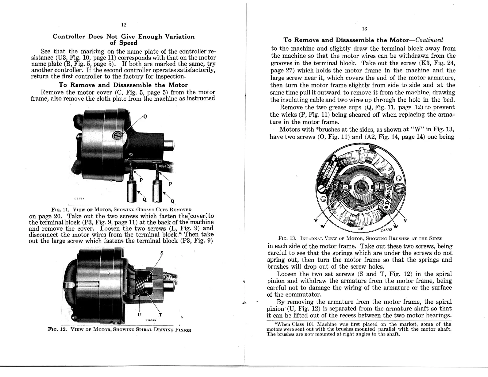
FIG. 11.
or
GREASE
on page 20. Take
out the two screws which fasten
to
the terminal
block (P3, Fig. 9, page 11) at
the
back
of the
machine
and remove the cover.
Loosen the two
screws
(L,
Fig. 9)
and
disconnect
the motor wires from the terminal
Then
take
out
the large screw which the
terminal
block
(P3,
Fig.
9)
To Remove
and Disassemble
the
to the machine and slightly draw the terminal block away from
the machine so that the motor wires can be withdrawn from the
grooves in
the terminal block. Take out the screw (K3, Fig. 24,
page 27) which holds the motor frame in the machine and
the
large screw near it, which covers the end
of the motor armature,
then turn the motor frame
slightly from side to side and
at the
same time pull it outward to remove it from the
machine, drawing
the insulating cable and two wires up through
the hole in the bed.
Remove the two grease cups (Q, Fig. 11, page
12) to prevent
the wicks (P, Fig. 11) being sheared off when
replacing the arma-
ture in the motor frame.
Motors with *brushes at the
sides, as shown
at “W” in Fig.
13,
have two screws (0, Fig. 11) and (A2, Fig. 14,
page 14) one being
Fm.
13.
OF THE SIDES
in each
side
of the
motor
frame. Take
out these two
screws, being
careful
to see that
the springs which are under the screws do not
spring
out, then turn the motor frame so that the springs and
brushes will drop out
of the screw holes.
Loosen the two set screws (S and T, Fig. 12) in the spiral
pinion
and withdraw the armature from the motor frame, being
careful not to damage the wiring of the armature or the surface
of the commutator.
By removing the armature from the motor frame, the spiral
pinion (U, Fig.
12) is separated from the armature shaft so that
it
can be lifted out
of the recess between the two motor bearings.
Machine first placed on the market, some of the
motors
were sent out
with the brushes mounted with
the motor shaft.
The brushes
are now
mounted at right angles
to shaft.
“Eur Moron,
Snowixc. (furs
REMOVED
thelcover.’
block.”
fastens
13
Motor—Continued
INTERNAL VIEW Moron, Snowmo lini'snizs AT
‘thn (‘luss
10] was
parallel
the
 Loading...