To Reassemble
and
Replace
the Motor
Place the spiral pinion (U,
Fig. 12) in the recess
between the
two bearings in the
motor
frame, being careful to have the teeth
of the spiral pinion toward the armature.
Then gently replace
the
armature in the motor
frame, passing the armature shaft
through the hole in the
spiral pinion (U). Push the armature
into the motor frame as
far
as it will go, then push the spiral
pinion against the inner bearing
(Z, Fig. 14)
in the motor frame,
being careful to see that there
is no grease or dirt between
the
pinion and
bearing.
Fasten the spiral pinion to the armature shaft by means
of
the two set screws (S and T, Fig. 12, page 12) tightening first
the set screw which bears against
the flat part of
the shaft.
To determine
the flat part
of the shaft for the spiral
pinion
set
screw, turn
the armature shaft until the
small fiat mill on its
end
is in line with the set screw in the spiral pinion, then tighten the
set screw.
It will be noticed that there is a bronze painted
mark
and
an
aluminum
painted mark on the outside of the motor frame
cast-
ing, and that one
of the brushes has
a small bronze painted
mark
on one of its sides, and the other brush an aluminum painted
mark.
When
replacing the brushes, care must be
taken to insert
the
brush which
is marked with bronze into the screw hole in the
side
of the motor marked with bronze, inserting the unmarked
end
of
the brush
in first with the marked side of the brush
facing
toward
the
marking
on the motor frame.
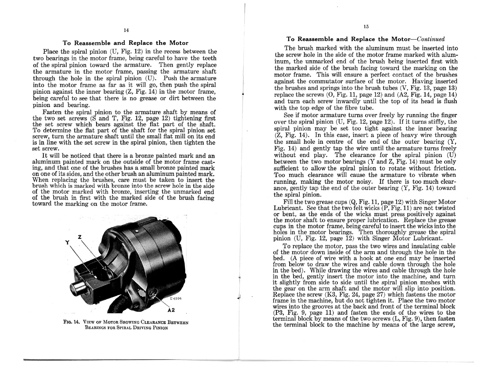
Fm. VIEW or
BETWEEN
To and Replace the
The brush marked with the aluminum must be inserted
into
the
screw hole
in
the side of the motor frame marked with
alum-
inum, the unmarked end of the brush being inserted first with
the marked side of the brush facing toward the marking on the
motor frame. This will ensure a perfect contact of the brushes
against the commutator surface of the motor. Having inserted
the brushes
and springs into the brush tubes (V,
Fig.
13, page 13)
replace the screws (0,
Fig. 11, page 12) and (A2, Fig.
14, page 14)
and
turn each screw inwardly until the top of its head is flush
with the top edge of the fibre
tube.
See if motor armature turns over freely by running the finger
over the
spiral pinion (U, Fig. 12, page 12). If it turns stiffly, the
spiral pinion may be set too tight against the inner bearing
(Z, Fig. 14). In this case, insert a piece of heavy wire through
the small
hole
in centre
of the end of the outer bearing
(Y,
Fig.
14) and gently
tap
the wire until the armature turns freely
without end
play. The clearance for the spiral pinion (U)
between
the two motor bearings (Y and Z, Fig. 14) must be only
sufficient to allow the spiral pinion to
rotate without friction.
Too much clearance
will cause the armature
to vibrate
when
running,
making the motor noisy. If there is too much clear—
ance,
gently tap the end of the outer bearing (Y, Fig. 14) toward
the spiral
pinion.
Fill the two grease cups (Q, Fig. 11, page 12) with Singer Motor
Lubricant. See that the two felt wicks (P, Fig. 11) are not twisted
or bent, as the ends of the wicks must press positively against
the motor shaft to ensure proper lubrication. Replace the grease
cups
in the motor frame, being careful to insert the wicks into the
holes in the motor
bearings.
Then
thoroughly grease the spiral
pinion (U, Fig. 12, page 12) with Singer Motor Lubricant.
To replace the motor, pass the two wires and insulating cable
of the motor down inside of the arm and through the hole in the
bed. (A piece of wire
with a hook at one end may be inserted
from below to draw the wires and cable down through the hole
in
the bed). While drawing the wires and cable through the hole
in the bed, gently insert the motor into the machine, and
turn
it slightly from side to side until the spiral pinion meshes with
the gear on the arm shaft and the motor will slip into position.
Replace
the screw (K3, Fig. 24, page 27) which fastens the motor
frame in the machine, but do not tighten it. Place the two motor
wires
into the grooves at the back and front
of the
terminal block
(P3,
Fig. 9, page 11) and fasten the ends of the wires to the
terminal block by means of the two screws (L, Fig. 9), then fasten
the terminal block to the machine by means of the large screw,
14
14. Moron
Snowmo CLEARANCE
Bnmluos ron
SPlRAL Dmvmc PlNION
10
Reassemble Motor—Continued
 Loading...