TO
ADJUST
THE
TRIMMER
(CONTINUED)
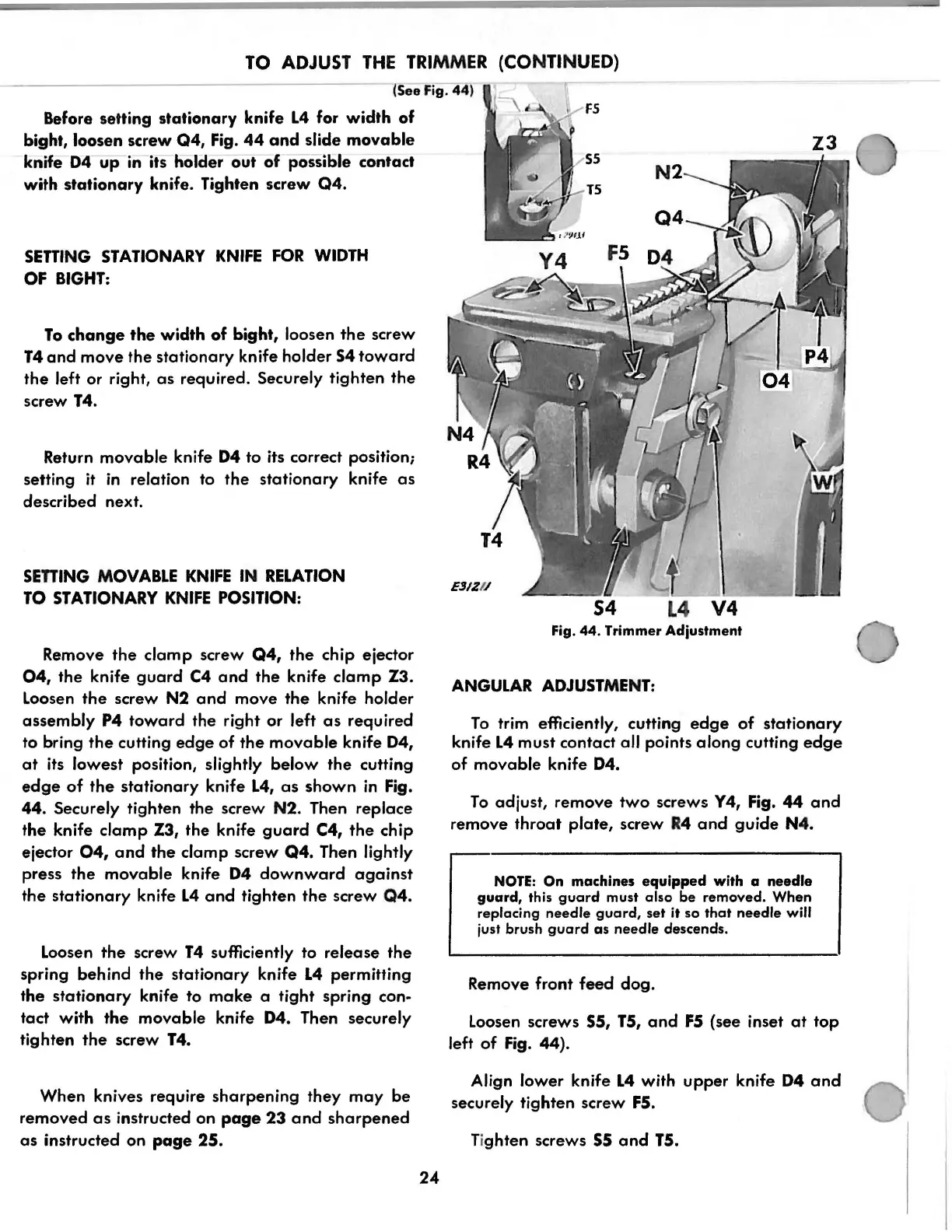
(See Fig. 44)
Before setting
stationary
knife
L4
for
width
of
bight, loosen screw Q4, Fig.
44
and
slide
movable
knife
04
up
in its holder
out
of
possible contact
with
stationary
knife. Tighten screw
Q4.
SETTING
STATIONARY
KNIFE
FOR
WIDTH
OF
BIGHT:
To
change
the
width
of
bight, loosen
the
screw
T4
and
move
the
stationary
knife holder
54
toward
the
left or right,
as
required. Securely tighten
the
screw T4.
Return
movable
knife
04
to its correct position;
setting
it
in
relation to
the
stationary
knife
as
described next.
SEniNG
MOVABLE
KNIFE
IN
RELATION
TO
STATIONARY
KNIFE
POSITION:
Remove
the
clamp
screw
Q4,
the
chip ejector
04,
the
knife
guard
C4
and
the
knife
clamp
Z3.
Loosen
the
screw N2
and
move
the
knife holder
assembly
P4
toward
the right
or
left
as
required
to
bring
the
cutting
edge
of
the
movable
knife
04,
at
its lowest position, slightly
below
the
cutting
edge
of
the
stationary
knife
L4,
as
shown
in
Fig.
44.
Securely tighten the screw N2. Then replace
the
knife
clamp
Z3, the knife
guard
C4,
the
chip
ejector
04,
and
the
clamp screw
Q4.
Then lightly
press
the
movable
knife
04
downward
against
the
stationary
knife
L4
and
tighten
the
screw
Q4.
Loosen
the
screw
T4
sufficiently to
release
the
spring behind
the
stationary knife
L4
permitting
the
stationary
knife to
make
a tight spring con·
tact
with
the
movable
knife
04.
Then securely
tighten
the
screw T4.
When knives require
sharpening
they
may
be
removed
as
instructed
on
page
23
and
sharpened
as
instructed on
page
25.
24
E31ZI/
L4
V4
Fig.
44.
Trimmer Adjustment
ANGULAR
ADJUSTMENT:
To
trim efficiently, cutting
edge
of
stationary
knife
L4
must contact all points
along
cutting
edge
of
movable
knife
04.
To
adjust,
remove
two
screws Y4, Fig.
44
and
remove
throat
plate,
screw
R4
and
guide
N4.
NOTE:
On
machines
equipped
with
a
needle
guard,
this
guard
must
also
be
removed.
When
replacing
needle
guard,
set
it
so
that
needle
will
just brush
guard
as
needle
descends.
Remove front
feed
dog.
Loosen screws 55, T5,
and
F5
(see inset
at
top
left
of
Fig. 44).
Align lower knife
L4
with
upper
knife
04
and
securely tighten screw
F5.
Ti
ghten
screws
55
and
T5.
From the library of: Superior Sewing Machine & Supply LLC