SIJTING
THE PRESSER BAR AT
THE
CORRECT HEIGHT
Accumulation of lint, oil and dirt on presser foot
may
prevent
proper
seating
of foot.
Clean
this
area
before
setting
the
presser
bar.
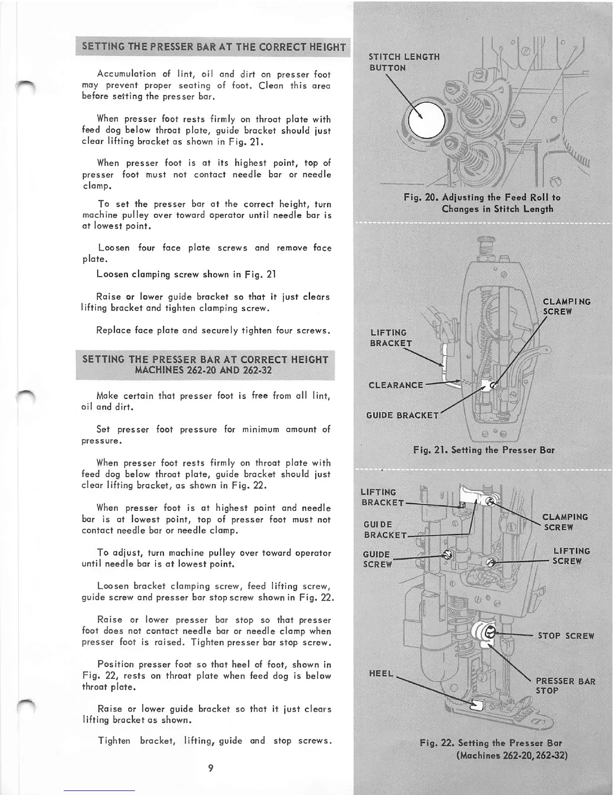
When
presser foot rests firmly on throat plate with
feed
dog
below throat plate, guide bracket should just
clear lifting bracket as shown in Fig. 21.
When
presser
foot Is
at
its
highest
point, top of
presser foot must not contact needle bar or needle
clamp.
To
set
the
presser
bar
at
the correct height, turn
machine pulley over toward operator until needle bar Is
at lowest point.
Loosen four face
plate
screws
and remove face
plate.
Loosen clamping screw shown in
pig.
21
Raise
or lower guide bracket so
that
it
just
clears
lifting bracket and tighten clamping screw.
Replace face plate and securely tighten four screws.
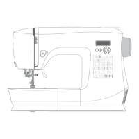
SETTING
THE
PRESSER
BAR
AT
CORRECT
HEIGHT
MACHINES
262.20
AND
262-32
Make certain that presser foot is free
from
all lint,
oil
and
dirt.
Set
presser
foot
pressure
for minimum amount of
pressure.
When
presser
foot
rests
firmly on throat
plate
with
feed dog below throat
plate,
guide bracket should
just
clear lifting bracket, as shown in pig. 22.
When
presser
foot is
at
highest
point and
needle
bar is at lowest point, top of
presser
foot must not
contact needle bar or needle clamp.
To adjust, turn machine pulley Over toward operator
until needle bar is
at
lowest point.
Loosen
bracket
clamping
screw,
feed lifting
screw,
guide screw and
presser
bar stop screw shown in
Fig.
22.
Raise
or lower
presser
bar stop so
that
presser
foot does not contact needle bar or needle clamp when
presser
foot is
raised.
Tighten
presser
bar
stop
screw.
Position
presser
foot so
that
heel of foot, shown In
Pig. 22,
rests
on throat plate when feed dog is below
throat
plate.
Raise or lower guide bracket so
that
it
just
clears
lifting bracket
as
shown.
Tighten bracket, lifting, guide and stop screws.
STITCH
LENGTH
BUTTON
r a !
Fig.
20.
Adjusting
the
Feed
Roll
to
Changes
In
Stitch
Length
LIFTING
BRACKET
CLEARANCE
^
GUIDE
BRACKET'
CLAMPING
SCREW
\ ...
..o
^
Fig.
21.
Setting
the
Presser
Bar
LIFTING
In
BRACKET
-^-1
"
11
GUIDE
GUIDE
screw'
;v-7i
i
.1^
-.fTT
nil
1!\mi
1
CLAMPING
SCREW
LIFTING
—
SCREW
i 1
STOP
SCREW
presser
bar
STOP
Fig.
22.
Setting
the
Presser
Bar
(Machines 262-20,262.32)