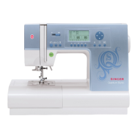
Do you have a question about the Singer QUANTUM STYLIST 9960 and is the answer not in the manual?
Crucial precautions to avoid damage from electrostatic discharges during servicing.
Menu for checking different sensors and switches in the machine.
Checks the buttonhole lever switches at the rear and front of the zigzag step motor.
Checks the timing and speed sensors on the right side of the upper shaft.
Checks the bobbin winder spindle position switch.
Checks the bobbin winder stopper switch for winding completion.
Checks the presser foot lifter switch.
Checks the thread sensor at the thread take up spring.
Tests the function of each hard key button on the front cover.
Checks the foot control pedal's response to pressure.
Checks the manual speed control slider on the front cover.
Instructions for removing the light cover.
Instructions for removing the top cover.
Instructions for removing the thread tension cover.
Instructions for removing the needle plate.
Instructions for removing the machine base.
Instructions for removing the front cover.
Instructions for removing the unit top cover.
Instructions for removing the rear cover.
| Stitch Applications | 600 |
|---|---|
| Built-In Needle Threader | Yes |
| Maximum Sewing Speed | 850 stitches per minute |
| Automatic Thread Cutter | Yes |
| Drop Feed | Yes |
| Extension Table | Yes |
| Type | Computerized |
| LCD Screen | Yes |
| Bobbin System | Top drop-in |
| Number of Buttonholes | 13 |
| Lettering Fonts | 5 |
| Buttonhole Styles | 13 |
| Stitch Width | 7mm |
| Stitch Length | 5mm |
| USB Port | No |
| Voltage | 110V |
| Warranty | 25-year limited warranty |
