Dear Users:
Thank you for your purchase of the Digital Display Meter, of which the
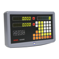
main purpose is provide detection and positioning functions for
machine tool processing. Before use, please read the following safety
instructions and precautions for safety operation of the new digital
display meter device.
When using the manual:
Chapters and sections are listed in the table of contents( see P11/12
ahead).
This manual includes some instructions for panel keys of series-2 digital
display meter and other series, including.
SDS2-2M
SDS2-2MS
SDS2-2G
SDS2-2L
SDS2-3M
SDS2-3E
Digital display meter for universal 2-axis milling machine
Digital display meter for multifunctional 2-axis milling
machine
Digital display meter for universal 2-axis grinding machine
Digital display meter for universal 3-axis grinding machine
Digital display meter for universal 3-axis milling machine
Digital display meter for universal 3-axis electric spark
molding machine tool
It is recommended that:
Instructions for panel keys of the series-2 digital display meter that is
applicable to this manual are listed in P1~10 of the above Section 1.
Read through follow safety precautions and Section 2( see P112,
113, 114), which are very important to the safe operation of your digital
display meter.
Safety Precautions:
Caution:
Do not dampen or splash coolant directly onto the unit to avoid electric
shock or fire.
Warning:
Do not open the enclosure optionally to avoid electric shock, there is no
element repairable by the user inside. Turn to appointed technician for
repair.