Do you have a question about the Sinope TH1400WF and is the answer not in the manual?
Step-by-step instructions for physically mounting and connecting the thermostat to the wall.
Diagrams illustrating how to connect wires for different heating systems.
Instructions for connecting an optional floor sensor for specific heating modes.
Guide for connecting the thermostat to the Neviweb app for remote control.
How to access and change thermostat settings manually via the device.
Details on parameters adjustable directly from the thermostat interface.
Details on parameters adjustable via the Neviweb app, including cycle lengths.
Electrical and operational specifications of the thermostat.
Details on the warranty coverage for the thermostat components.
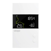
The Sinopé TH1400WF is a Smart Low Voltage Thermostat (24 Vac) designed for controlling various heating systems, including electric baseboards, hot water valves, and floor heating systems. It offers both ambient (A mode) and floor (F mode) temperature regulation, with the ability to limit floor temperature using an external sensor. The thermostat is Wi-Fi certified, allowing for remote control and monitoring through the Neviweb app for iOS and Android.
The TH1400WF thermostat provides precise temperature control for residential heating systems. It operates on a 24 Vac power supply and can manage a maximum load of 1 Amp. The device features an auxiliary heating output that can act as a second stage of heating when controlling ambient temperature. This auxiliary output activates if the room temperature is significantly below the setpoint or if the main heating stage struggles to raise the temperature effectively. Both the main and auxiliary outputs can control different types of heating loads and are configurable in the user settings.
The thermostat supports two primary temperature control modes:
For hydronic heating systems, the thermostat includes a circulator pump's anti-seizure feature. If the thermostat does not call for heat for an extended period, this parameter will activate the main output for 1 minute every 24 hours to prevent the hydronic system pump from seizing.
The TH1400WF can be installed by unlocking and lifting the thermostat cover, marking and drilling fastening holes if necessary, inserting wires into terminals, fixing the base to the wall, replacing the cover, and then powering up the thermostat.
All thermostat settings can be configured through the Neviweb app. For users who prefer manual configuration or have not yet set up their Neviweb account, settings like temperature format (°C or °F) and control cycle length can be adjusted directly on the device. To access the menu, users need to lower the setpoint to its minimum and hold the "down" button for 10 seconds. Navigation is done using the "up" and "down" buttons, and settings are saved by pressing the "up" and "down" buttons simultaneously.
Key configurable parameters include:
The thermostat also supports HomeKit, allowing for control through Apple's ecosystem. For automatic control and remote access with HomeKit, a HomePod, Apple TV, or iPad set up as a home hub is required.
To disconnect the thermostat from the Wi-Fi router or the Neviweb app, users can press the "up" and "down" buttons simultaneously for 10 seconds. The Wi-Fi symbol will disappear from the display. To completely remove the thermostat from Neviweb, the "Delete" option within the thermostat settings in the app should be used.
The device comes with a 3-year limited warranty from Sinopé Technologies Inc., covering defects in material and workmanship under normal use and service, provided proof of purchase is supplied. This warranty does not cover transportation costs, improper installation, misuse, or accidental damage.
The TH1400WF is designed to be a reliable and user-friendly smart thermostat, offering advanced control options for various heating setups while ensuring energy efficiency and comfort.
| Brand | Sinope |
|---|---|
| Model | TH1400WF |
| Category | Thermostat |
| Language | English |