12
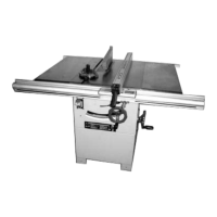
9.2. Cross-cut fence
• Push the slot stone of the bracket (2) for the
cross-cut fence into the T-slot (1) at the sliding
table.
• Loosen the locking screws (3) on the bracket
on the
work piece downholder and on the
bracket for the cross-cut fence.
• Push the slot stones into the T-slot (4) on the
cross-cut fence (5).
• Tighten the locking screws (3) again.
• By means of the scale (6) you can set the
cross-cut fence at any angle to the saw blade.
• Mount the stopper (7) onto the cross-cut
fence.
• Loosen the slot stone of the stopper (7) with
the winged screw (8) until it can be inserted
into the T-slot (9) of the cross-cut fence.
• The stopper (7) can be moved along the T-slot
at the cross-cut fence into the desired
position and fixed again with the wing screw
(8).
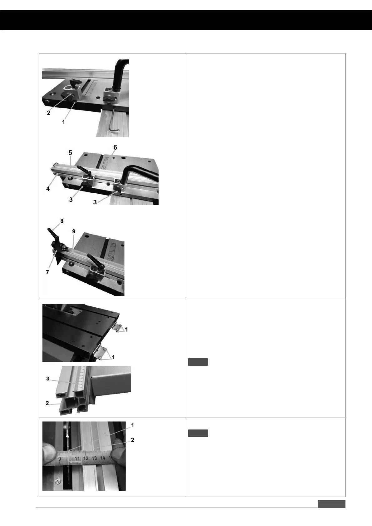
10. Assembly guide profiles
At the work table there are brackets at the front
and at the rear where the guide profiles are
attached.
• Loosen the nuts (1) of the 2 screws of each
bracket until their heads can be inserted into
the T-slot of the guide profile.
NOTE: Ensure that the wide slot (2) of the guide
profiles is located lateral outside and that the
ruler (3) of the guide profile for the rip fence
faces upwards.
10.1. Adjustment of sliding table
NOTE: Make sure that the measuring scale (3) on
the rip fence guide profile is adjusted to the saw
blade.
• Measure the distance between saw blade (1)
and rip fence (2).
5. ASSEMBLY Cont...
 Loading...