71
3.3 Seitliche Transportstellung mit
erhobenem Messerbalken
3.3 Transport position at the side of
the tractor with lifted cutter bar
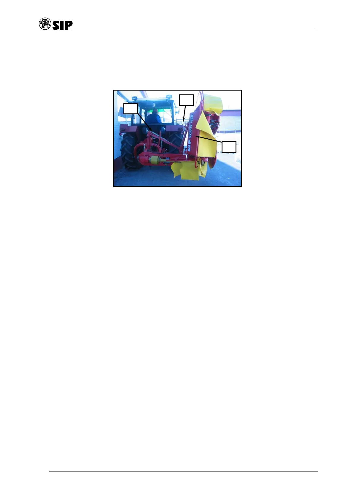
Bild - Figure 13
Die Maschine in Arbeitsstellung und auf dem
Boden
• Messerbalken (1) durch Einschaltung des
Hydrauliksystems aufheben.
• Die Maschine mit
Dreipunkthydraulikgestänge aufheben.
• Sperrventil (2) in Stellung geschlossen
setzen.
• Arretierungshebel (3) in Transportstellung
setzen.
The machine in work position and on the ground
• Lift the cutting bar (1) by switching on the
hydraulic system.
• Lift the machine with three point hydraulic
hitch.
• Set the stop valve (2) into position closed
• Set the arrest lever (3) into transport
position
Die Maschine in seitliche Transportstellung mit
erhobenem Messerbalken
• Sperrventil (2) in Stellung offen setzen.
• Messerbalken (1) durch Einschaltung des
Hydrauliksystems herunterlassen.
• Die Maschine mit
Dreipunkthydraulikgestänge herunterlassen.
The machine in transport position at the side
with lifted cutting bar
• Set the stop valve (2) into position opened
• Lower the cutting bar (1) by switching on the
hydraulic system.
• Lower the machine with three point
hydraulic hitch.
3
2
1
 Loading...