This document describes the ORTHOPHOS XGPlus DS / Ceph, ORTHOPHOS XG 5 DS / Ceph, and ORTHOPHOS XG 3 DS X-ray units, which are digital systems (DS) designed for dental radiography. The manual covers general information, messages, troubleshooting, adjustment, service routines, repair, and maintenance.
Function Description
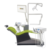
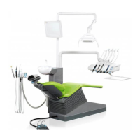
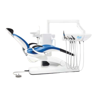
The ORTHOPHOS XG series X-ray system is designed for panoramic and cephalometric (Ceph) radiography. It comprises several main modules: a slide with a rotary unit, a stand, an optional cephalometer (which can be arm-mounted on either the left or right side), and an optional remote control.
The XGPlus system class features a control panel with a color touchscreen (Easypad), offering both a basic and a full version. The full version includes advanced programs and functions such as constant magnification factor (1.25 for P2C, P10C), artifact-free display (P1A, P2A, P10A), selectable right/left partial views and individual quadrants (P1A, P2/A/C, P10/A/C, P12), selectable upper/lower jaw partial views and individual quadrants (P1/A/C, P2/A/C, P10/A/C), temporomandibular joint views (TM2, TM3, TM4, TM5, TM6), sinus views (S2, S3, S4), selectable "jaw shape" program settings, Quickshot function (for Pan and Ceph), orthodontic image series (P1-C3-C4 without cooling periods), TSA configuration level (with optional TSA operation), a welcome screen with patient data from SIDEXIS (V01.50 and higher), and specific shadowing features for Ceph programs (C3, C3F, C1, C2).
The XG 5 / 3 / 3 PPE basic class is equipped with a simpler control panel with a single-line display (Multipad). The XG 5 system version offers 8 panoramic programs (P1, P1C, P10, P1L, P1R, TM1.1/TM1.2, S1, MS1) and 5 Ceph programs (C1, C2, C3, C3F, C4). Its functions include half-views of right/left sides (only with P1, not upper/lower jaw), a constant magnification factor of 1.25 (only with P1), but no Quickshot function, no "jaw shape" program presetting, no artifact-free display mode, no orthodontic image series without cooling periods, no TSA configuration level or operation, and no welcome screen. The XG 3 and XG 3 PPE (pay per exposure, USA only) versions offer 5 panoramic programs (P1, P1C, P1L, P1R, TM1.1/TM1.2) with similar functional limitations as the XG 5, including no Ceph programs.
All ORTHOPHOS XG units are digital systems (DS). Remote control operation is possible in all system versions.
Important Technical Specifications
- Rated Line Voltage: 200 V - 240 V, 50/60 Hz.
- Permissible Line Voltage Fluctuations: 200 - 230 V: ± 10%.
- Internal Line Impedance: Must not exceed max. 0.8 Ω.
- Warm-up Time: Approximately 1 minute after switching ON.
- Cooling Period: Maintained by an automatic exposure blocking function based on the pulse/pause ratio (1:10, i.e., 10-second pause for each second of radiation emission). A 1:20 pulse/pause ratio is better for the X-ray tube.
- Turn-off Time: Must be at least 60 seconds.
- Software Versions: The overall system software version is determined by the software statuses of the EEPROMs on the boards. Specific software versions are listed for ORTHOPHOS XG 3 PPE, ORTHOPHOS XG 3, ORTHOPHOS XG 5 / Ceph, and ORTHOPHOS XGPlus / Ceph, along with compatible SIDEXIS XG versions.
- Hardware Versions: Board DX41 is omitted in units with hardware version BA or higher (as of November 2006).
Usage Features
- User Interface: XGPlus units use a color touchscreen (Easypad), while XG 5 / 3 / 3 PPE units use a single-line display (Multipad).
- Demo Mode: Allows operation without radiation release, essential for presentations or exhibitions. This mode is activated by setting dip switch S2 (DX6) to position 2 and disconnecting cable L5 (X-RAY) from connector J6 (DX6). Starting with SW V02.28, the complete possible functionality of the system class is simulated in demo mode.
- Self-adjustment Routine: Executed automatically upon power-on. Pressing a button during this routine will display an error message.
- Error Messages: Displayed on the Multipad (XG 5 / 3 / 3 PPE) or Easypad (XGPlus) touchscreen. Error codes provide information on error type, location, and troubleshooting.
- Service Menu: Accessible via a specific key combination on the Easypad or Multipad, allowing access to various service routines for system settings, tests, and compensations. Security access is required for routines involving radiation release or configuration data editing.
- Adjustment Menus (SIDEXIS XG): The Diaphragm/system adjustment menu (password-protected) guides through panoramic and cephalometer adjustments. It offers coarse and precision adjustment modes, with precision adjustment being the preferred method.
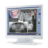
- Image Acquisition: Initiated via the "Image Acquisition" button in SIDEXIS XG after selecting the desired service exposure.
- X-ray Image Evaluation: Test images (PAN, CEPH, TSA) are generated and evaluated for tile structure, linear grayscale gradient, clear intensity steps, and absence of artifacts.
Maintenance Features
- Software Update: Performed using the SIXABCON utility program in the SIDEXIS XG program folder. Important information regarding permissible software updates and potential downgrades is provided, including specific serial number ranges for which downgrades are not allowed.
- Error Logging Memory (S007): A component of "Extended Details" in SIXABCON, it stores error data to aid in troubleshooting.
- CAN Bus Check (S012): Diagnostic function on board DX1 via LEDs (V700, V701) to check CAN bus operating status and identify communication errors. Jumper positions on board DX1 are crucial for correct CAN bus function.
- Board Checks: Visual inspection of boards and LEDs, voltage measurements, and continuity tests (unit OFF) are recommended.
- Motor Checks: Visual inspection of motors and plug connections, and functional checks.
- Light Barrier Checks: Manual actuation of light barriers and checking signal changes on connectors.
- Device Leakage Current Check: Measurement of leakage current according to IEC 601 requirements.
- Cable Checks: Visual inspection of power, ground, control, and data cables for damage, proper shielding, and correct routing.
- Replacing Components: Detailed instructions for replacing various components including height adjustment motor, ring motor, PAN actuators, headrest, Easypad/Multipad, control panel, light localizers (FH, MS, Ceph), support piece, motor-driven diaphragm, fixed diaphragm, X-ray tube assembly, fan, PAN (TSA) sensor holder, ceph sensor holder, sensor, light barriers, circuit boards (DX1, DX11, DX32, DX41, DX42, DX61, DX71, DX81, DX91), and cables.
- Post-Replacement Measures: After replacing boards or modules, it is crucial to check software compatibility, perform software updates/downgrades, confirm unit serial numbers, and perform complete system adjustments (PAN, TSA, CEPH).
- Routine Maintenance: Includes checking height adjustment (for abrasion, running noises, limit switch function), forehead and temple supports (for smooth movement), sensor holders (for secure seating), support piece (for secure fitting of bite block), light localizers (for alignment), X-ray images (for quality), tube data (kV, mA, fan, temperature), diaphragm (test exposures), cables (for damage), idling rollers (for smooth running), grounding straps (for firm contact), cable shields (for proper contact), and protective ground wires (for resistance).