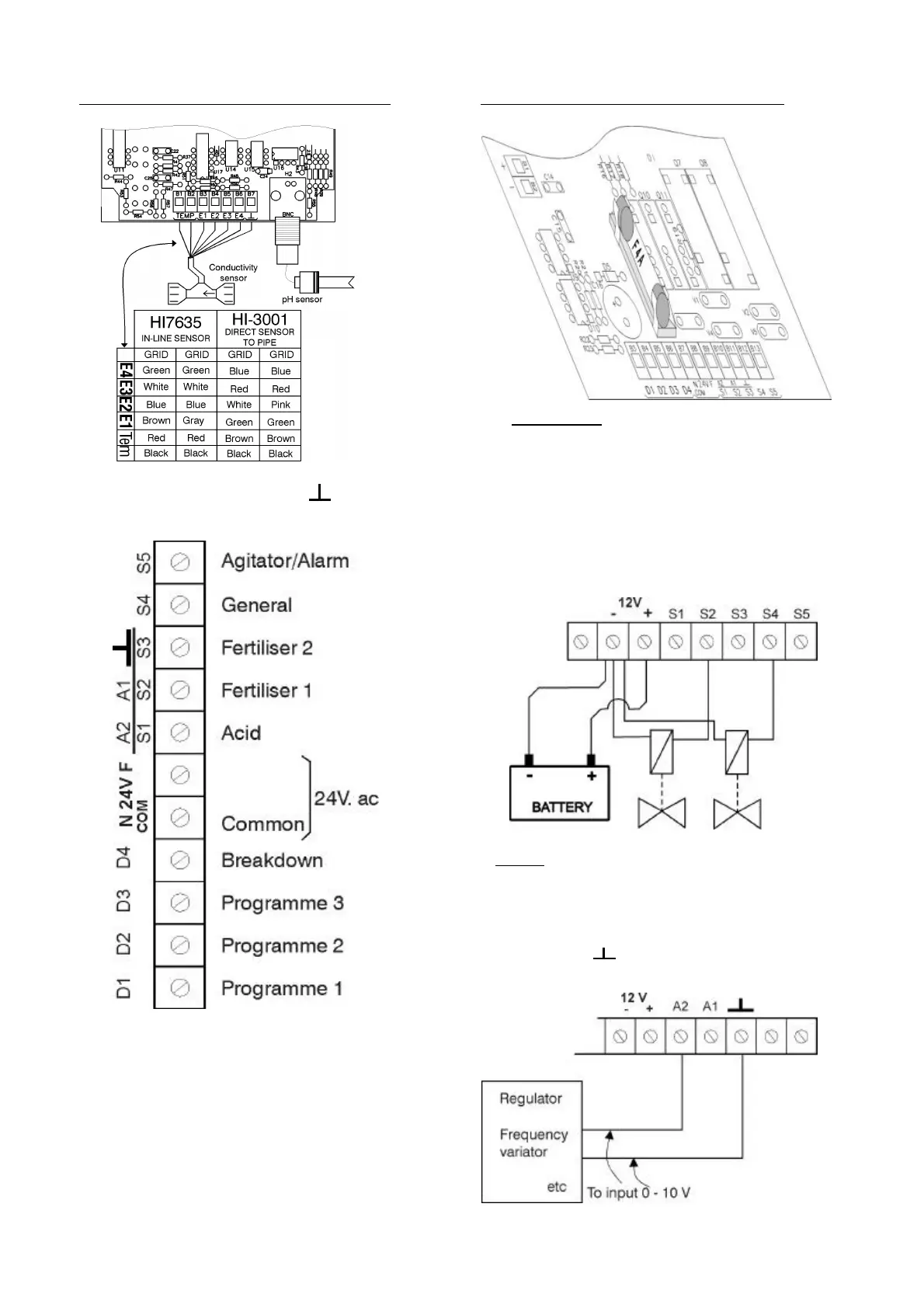
SECTION OF THE UNIT SUPERIOR BOARD
VERY IMPORTANT: The grid must be
connected to the box terminal of the unit.
6.2 OUTLETS
The unit has 5 outlets, 2 of them are digital and
the other 3 can be digital or analogical, depending
on the chosen version.
Outlets are protected by a 2.5 A fuse Type F
(fast). Replace it with a similar one if it fuses.
SECTION OF THE UNIT INFERIOR BOARD
- S1, S2 and S3: Digital outlets for the injection of
acid or base and fertiliser by pulses. The acid or
base electrovalve is connected to S1, the
fertiliser number 1 electrovalve to S2 and the
fertiliser number 2 electrovalve to S3.
- Electrically, the electrovalves will be connected
directly to the outlets without any relay in
between and hydraulically they will be
connected to the venturis or to the magnetic
pumps.
- A1, A2: Analogical outlets from 0 to 10 volts to
connect to frequency variators or regulators. It is
important neither to short-circuit these signs nor
to put the cables near power lines. Outlet A1
corresponds to fertiliser and A2 to acid or base.
The symbol is the common outlet or 0
volts.