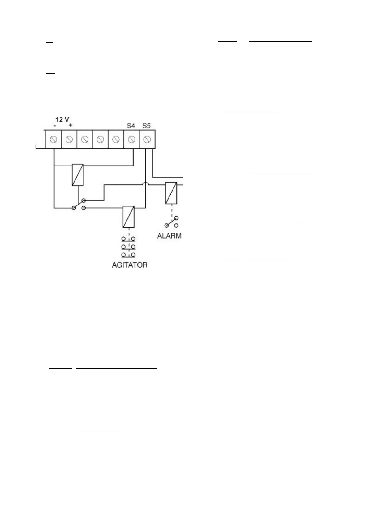
- S4: Digital outlet, which is activated during the
whole irrigation, except when there is a
breakdown.
- S5: Digital outlet used both for the start and stop
of agitators and for breakdown detection. For a
shared use of both functions, it is necessary to
use a relay activated by the general outlet. If it is
activated, the agitators will work, but if it is
deactivated, the alarm device will work.
7. CONFIGURATION OF THE INSTALLER
This configuration must be done by the unit
installer. Press the “+” and “-“ keys at the same time
to access it. Press the “C” key to go to the following
code. Press the “+” and “-“ keys to change the
values. Press the “C” key until the C0 code is
displayed to go back to CONSULTATION.
- Code 00: Delay until the first regulation. Indicate
the time in seconds that the programmer must
wait to calculate the regulation when a
programme is started. During this time, the % of
applied injection will be the one memorised in
the last irrigation. This allows the injection
stabilisation. The value must be between 0 and
250.
- Code 01: Reaction delay. Indicate the time in
seconds that the programmer must use to carry
out the adjustment to be done. The maximum
time is 5 seconds. Time 0 indicates that the
adjustment must be done as soon as it is
detected.
- Code 02: Self adjustment delay. Indicate the
time in seconds that must go by between a self-
adjustment attempt and the next one. The self-
adjustment is a small increase or decrease of
the % of injection which is introduced when the
sensor value is outside the programmed
reference value but within the allowed error.
The minimum time is 4 seconds and the
maximum is 15.
- Codes 03, 04 and 05: Proportional bands. The
limits, within which the % of injection will be
calculated, must be indicated in these three
codes, one for every programme. The lower the
limit, the more abrupt the changes will be when
trying to obtain the desired reference. The value
can be between 0 and 9.9, although the normal
is 2.0.
- Code 06: Modulation cycle (*). Indicate, in
seconds, the frequency in which the injection
impulses will be repeated. A suitable value
would be between 2.0 seconds and 4.0
seconds, although it can go from 2.0 to 9.9
seconds.
- Codes 07, 08, 09 and 10: Delay. Indicate, in
seconds, the time that has to go by from the
moment the activation of an input is detected
until the programmer takes it into account. The
value must be between 0 and 250.
- Code 11: Acid o base. In this code it can be
selected how it will work the pH regulation in
the irrigation water, by means of acid or base. If
it leaved the value to 0 it will work like an acid,
and if it is modified with the “+” key and leaved
to 1 it will work like a base. Then, it will be
determinate if there is an acid or base tank.
(*) In the “by impulse” version, to maintain the CE, the unit
applies every certain seconds, a dose of every fertiliser, which is
related to the desired proportion between fertilisers and the
programmed reference. To maintain the pH the unit works in a
similar way. In the “analogical” version, to maintain the CE
and/or the pH, the unit changes the injection speed of the engines
until it gets the programmed references.
 Loading...