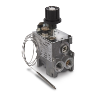
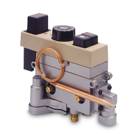
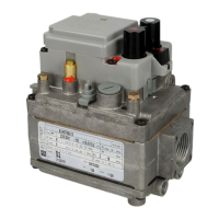
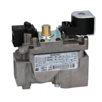
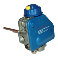
The 630 EUROSIT is a multifunctional gas control designed for various gas appliances requiring temperature control, such as space heaters, convectors, storage water heaters, boilers, and catering equipment. It operates without the need for an external power supply.
Function Description
The 630 EUROSIT is a single-knob multifunctional control that integrates several key features:
- Thermoelectric Safety Device: Ensures safe operation by monitoring the flame.
- Interlock Device: Prevents improper ignition operation, enhancing safety.
- Pressure Regulator: Manages gas pressure for consistent performance.
- Combined Modulating-ON/OFF Thermostat: Offers both modulating temperature control and snap-acting ON/OFF functionality, particularly at low settings.
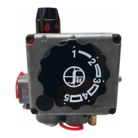
The single-knob control allows for temperature adjustment, pilot light operation, and turning the device off.
Important Technical Specifications
Gas Connections:
- 3/8" NPT X 3/8" NPT threaded inlets and outlets.
- Pilot outlet suitable for 3/16" or 1/4" tubing.
- Inlet and outlet pressure test ports.
Mounting Position:
- Multipoise, allowing for flexible installation.
Gas Types:
- Compatible with Natural Gas (NG) and Liquefied Petroleum Gas (LPG).
Maximum Inlet Pressure:
Outlet Pressure Setting Range (NG):
- 3.5" to 8.0" W.C. (Water Column).
Working Temperature Range:
Capacity (Natural Gas):
- No Pressure Regulator: 55,000 BTU/hr.
- Pressure Regulator: 40,000 BTU/hr.
- For Propane (LPG), multiply NG capacities by 1.62.
Pilot Flow Rate:
- 2.5 °F³ /hr at 0.5” Pressure Drop.
Thermostat Features:
- Thermostat Range 55-100 °F:
- 'a' (low setting): 2.7
- 'b' (high setting): 2.7
- 'c' (snap action): 1.8
- Thermostat Range 55-118 °F:
- 'a' (low setting): 4.5
- 'b' (high setting): 4.5
- 'c' (snap action): 2.7
- Other ranges are available upon request.
Usage Features
Start-up Procedure:
- Turn the knob to the OFF position and wait 5 minutes.
- Turn the knob to the PILOT position.
- Depress the knob and light the pilot, holding the knob down for approximately 60 seconds.
- Release the knob and verify the pilot flame remains on. If it extinguishes, repeat the ignition steps.
Temperature Setting:
- Turn the knob to the desired temperature. The maximum temperature is achieved by turning the knob fully counter-clockwise (HI position).
Temporary Shut-down Procedure:
- To turn off only the main burner, turn the knob clockwise to the PILOT position.
Complete Shut-down Procedure:
- Turn the control knob to the OFF position.
Safety Warning:
- The control features an interlock device. After shutting off all gas flow, the pilot burner cannot be relit until the thermocouple has cooled and the electromagnet has released (approximately 60 seconds).
- The gas control knob is designed for manual use only; do not use tools, as this may cause damage or injury.
Maintenance Features
Pressure Readings:
- Inlet Pressure: Turn the captured screw (6) counterclockwise 2 or 3 turns, then place a tube from a gauge over the test point.
- Outlet Pressure: Use the same method with captured screw (7).
- Warning: After readings, turn captured screws clockwise firmly to reseal; do not overtorque.
Setting the Thermostat:
- The thermostat is factory-set and sealed and is not field-serviceable.
Gas Flow (Vented Units Only):
- Maximum Flow Rate: Cool the thermostatic bulb below room temperature and turn the knob (4) counterclockwise to the HI position.
- Minimum Flow Rate: Cool the thermostatic bulb below room temperature, slowly turn the knob counterclockwise, and stop when a snap is heard. This rate is preset by the OEM with a pre-drilled minimum rate screw.
Pilot Adjustment (Vented Units Only):
- Use a screwdriver to adjust screw (5) to achieve the desired pilot flame. Turning clockwise decreases gas flow to the pilot.
Installation Guidelines:
- Installation, calibration, and regulation must be performed by qualified personnel following the instructions in the catalog and appliance manual.
- The control is not field-serviceable; all adjustments must be made at the OEM factory.
- Mechanical Connections: Do not tamper with sealed parts, loosen screws, or remove labels. Avoid shocks. Remove dust caps only at installation. Do not exceed recommended torque values. Ensure gas flow follows arrows on the valve body. Prevent foreign matter from entering the valve. Mount using the three mounting holes.
- Main Gas Connection: Use properly reamed pipes with 3/8" NPT thread. Apply moderate, good-quality pipe dope and 23 Lb./Ft. of torque. Close unused inlets/outlets with provided plugs, tightening to 5.2 Lb./Ft. Do not overtorque.
- Pilot Gas Connection: Connect pilot gas tubing using proper 1/4" or 3/16" shear-off nut and olive. Tighten finger-tight plus one turn with a wrench.
- Thermocouple Connection: Insert the threaded end of the thermocouple into the control. Tighten the fixing nut finger-tight plus 1/4 turn with a wrench.
- Testing: After all connections, check for leaks and ensure the appliance functions correctly.
Accessories (Available upon request):
- Cover
- Cover with piezoelectric ignitor
- Pilot shear-off nut and olive
- Remote adaptor
- Cables for piezoelectric ignitor
- Threaded plugs to close unused inlets and outlets